Tron General Instructions
Tron (8/9) (Bally Midway, 1982) · Manual · 70 pages · 65 sections · original scan
TRON
General Instructions
Csilly MIDWAY MFG. CO.
GENERAL INSTRUCTIONS
For
TRON
INSTALLATION
- Unlock and open the coin box door.
- Remove four (4) "CABINET LEVELING LEGS" from inside the coin box.
- Tip the cabinet to the side and remove the shipping cleats from its bottom.
° Locate the threaded holes - one in each corner - and install the "CABINET LEVELING LEGS" in them.
° Level the cabinet.
° When finished, the cabinet should be stable in the upright position.
- Plug the game into a standard A.C. wall outlet ONLY!
Game MUST be properly grounded.
- The power ON/OFF switch is located:
° UPRIGHT MODEL: On top of the cabinet toward the back.
° MINIT MODEL: In the center of the cabinet back just below the rear access door.
° COCKTAIL TABLE MODEL: Underneath the cabinet on Player No. 2's side.
LINE VOLTAGE SAFETY INTERLOCK SWITCHES
Line voltage SAFETY INTERLOCK SWITCHES have been provided for your protection. The locations of these SAFETY INTERLOCK SWITCHES are:
1, UPRIGHT MODEL: Inside the rear of the cabinet on the left side of both rear access doors as you face them,
PART NO. M051-00628-A010
- MINI MODEL: Inside the rear of the cabinet on the left side of the rear access door as you face it.
- COCKTAIL TABEL: Inside the cabinet on the hinge side of the coin door.
When the cabinet access door(s) are secured in place, the SAFETY INTERLOCK SWITCH plunger(s) are in a fully depressed condition. The game circuit can function normally.
When any cabinet access door(s) are opened, the SAFETY INTERLOCK SWITCH plunger(s) are in a partially extended condition. This isolates the game circuit from the line voltage.
To restore power to the game circuit with the access door(s) open, gently pull the SAFETY INTERLOCK SWITCH plunger(s) out to the fully extended condition. THIS IS TO BE USED FOR SERVICING THE GAME ONLY!
SELF-TEST
A slide switch is provided to make the game run a "Self-Test" on itself. The SELF-TEST SWITCH is located just inside the cabinet on the right side of the coin door frame as you face it.
To put the game into the Self-Test mode; turn the game ON and let it warm up for a few minutes. Then slide the SELF-TEST SWITCH to the ON position and actuate the "TILT" switch on the back side of the coin door just below the door lock to obtain the Self-Test-Menue display on the monitor screen.
When in the Self-Test mode, the monitor screen will display the results of certain test functions the game has run on itself. (These will be discussed in more detail later.)
TO SERVICE THE CONTROL PANEL(S)
- UPRIGHT MODEL:
° The control panel is held in place by two latches, one on the left side and one on the right side of the cabinet.
They are spring loaded to provide constant positive pressure on their latch plates.
They can be reached through the coin door AFTER turning power to the game off.
To release the latches, Lift up and toward the center of the control panel.
Once they are released, unhook them from their Latch plates.
To remove the control panel:
Raise it up and tilt it toward you until you can see the cable behind it.
Cradling the coitrol panel between yourself and the cabinet, disconnect Lt from Its cabling.
The control panel is now free and can be removed.
° To reinstall the control panel, reverse this procedure.
- MINI MODEL:
° The control panel is held in place by two latches, one on the left side and one on the right side of the cabinet.
They are spring loaded to provide constant positive pressure on their latch plates.
They can be reached through the coin door AFTER turning power to the game off.
To release the latches, lift up and toward the center of the control panel. Once they ere released, unhook them from their latch plates.
To remove the control panel:
Raise it up and tilt it toward you until you can see the cable behind it.
Cradling the control panel between yourself and the cabinet, disconnect it from its cabling.
The control panel is now free and can be removed.
° To reinstall the control panel, reverse this procedure.
- COCKTAIL TABLE MODEL:
° Each control panel is held in place by several screws, two on the inside of the cabinet and three along the bottom edge of the control panel.
Turn the power off to the game.
Open the coin box door and release the two latches on the inside of the cabinet up next to the table top.
Once they're released, unhook them from their latch plates.
Grasp the table top in the center above the coin door lifting up and to the side to tilt it open.
Remove the screws which secure the control panel in place.
° To remove the control panel(s):
Disconnect it from its cabling.
The control panel is now free and can be removed.
° To reinstall the control panel(s), reverse this procedure.
REMOVAL OF THE MAIN-DISPLAY-GLASS AND/OR THE T.V. BEZEL ASSEMBLY
- UPRIGHT MODEL:
Turn the power to the game off and remove the control panel. This gets the control stick out of the way so the main-play-glass can be removed.
Remove the screws securing the windshield retainer (at its top edge) and the windshield {at its bottom edge) in place and lift out the windshield.
By putting your finger in the hole in the middle of the main-display-glass support, you can lift it up and out.
Loosen the screws which secure the T.V. bezel-glass-clamps in place.
Move the clamps to the side and the bezel glass may be removed.
Remove the above mentioned screws and the bezel with four bezel-glass-clamps may be removed.
To reinstall the T.V. bezel asssembly and the main-display-glass, reverse this procedure.
- MINI MODEL:
Turn the power off to the game and remove the control panel.
Remove the screws which secure the glass clamping plate.
Lift out the glass clamping plate. This frees the main-display-glass soit can be Lifted up.
By putting your finger in the hole in the middle of the main-display-glass support, you can lift it up and out.
° Remove the screws which secure the T.V. bezel assembly and Lift it out. See Figure 47.
° Reverse this rocedure to reinstall the T.V. bezel assembly and the main-display-glass.
- COCKTAIL TABLE MODEL:
Remove the screws which secure the table top glass clamps in place.
Remove the table top glass.
Lift out the T.V. bezel assembly.
TO eepnstall the T.V. bezel assembly and the table top glass, simply reverse this procedure.
VOLUME CONTROL POT
The volume control pot is Located just inside the cabinet on the RIGHT side of the coin door frame. For adjustment, it may be reached through the coin door on ALL models.
To make the sounds louder, turn the pot clockwise (~>s) as you face it.
To make the sounds less loud, turn the pot counterclockwise (#~—%) as you face it.
VOLTAGE CONTROL POTS
The voltage control pots are located on the Linear Power Supply P. C. Board. They are preset at the factory and SHOULD NOT be tampered with at all unless the distributors service department is contacted first.
SELF-TEST
The Self-Test mode is a special mode for checking game play statistics as well as game switches and computer functions. It is the easiest and best way to check for proper operation of the entire game.
You may begin a Self-Test at any time by sliding the Self-Test switch to the "ON" position after the power to the game is on (Self-Test switch located just inside cabinet on right side of coin door frame), When this is done, the game will react as follows:
- If the game is in the Attract mode when the Self-Test switch is moved to the "ON" posi-
tion, it will finish the sequence and then go into the Self-Test mode. This is illustrated by the display of the Self-Test Mode Menue on the monitor screen.
- If the game is in the Ready-To-Play mode or the Play mode when the Seif-Test switch is slid to the "ON" position, it WILL NOT go into the Self-Test mode until AFTER the players last Tron has been eliminated (the game MUST be over). At this point, the game will ao into the Self-Test mode. Again, this is illustrated by the display of the Self-Test Mode Menue on the monitor screen.
- The fastest way to enter the Self-Test mode is to slide the Self-Test switch to the "ON" position and then activate the "TILT" switch located on the back side of the coin door just below the lock mechanism. The game will then IMMEDIATELY go into the Self-Test mode.
The Self-Test mode has eight (8) major catagories as illustrated by the following Figure of the Self-Test Mode Menue as it should appear on the monitor screen.
- It is easy to select what catagory you want to enter. By pushing forward or pulling backward on the controler stick, the Cursor at the left of the screen can be moved UP and DOWN, (forward=UP) and (backward=DOWN), until it is in front of the catagory you want to test. Release the controler stick at this time.
- After the Cursor has been positioned, pull the trigger on the controler stick (Upright and Mini models) or depress the fire button on the console (cocktail models) and the monitor screen will display the test catagory you have selected,
° Once you are IN one of the Self-Test mode catagories, FOLLOW THE ON-SCREEN INSTRUCTLONS TO COMPLETE THE TEST.
3, The next group of Figures show the CORRECT screen presentation for EACH catagory of the Self-Test mode.
The first display of the Self-Test mode is the Self-Test-Mode-Menue. It should look Like this:
SELECT DESIRED TEST
SELF DIAGNOSTICS SOUNDS PLAYER INPUT BOOKKEEPING MACHINE SETUP CHANNEL TEST PRESET GRID DISPLAY DYNAM UWUNns
(MENUE - CONTINUED)
POSITION CURSOR BY USING JOYSTICK UP AND DOWN
HIT FIRE BUTTON FOR TEST
During the SELF DIAGNOSTICS section of the Self-Test mode, you will first see a lot of different colored bars shown on the monitor screen. These bars will be UNpainted one at a time from the top down. Second, you will see the screen painted Red, Blue, and Green in bars from the top down. Third, another group of colored bars is displayed. This sequence is repeated several times. And finally, this sequence is replaced by this message: "HIT FIRE BUTTON TO EXIT".
If the SELF DIAGNOSTICS find one or more bad ROM or RAM chips: instead of goina through what is described above, the game will give you a written message as to which parts are bad.
During the SOUNDS section of the Self-Test mode, the game will give a display which looks like the following:
SELECT A SOUND
ALL SOUNDS EXIT THROW DISK HI GEAR HORZ LOW GEAR HORZ HI GEAR VERT LOW GEAR VERT MISSEL FIRE BONUS BASE 10 TILT 11 ALL MCP BLOCKS HIT 12 10 TOWER MUSIC 13 COIN 14 SUCCESS MUSIC 15 FAIL MUSIC 16 ATTACK SOUND WO DBINAUEWNH
17 TANK HORZ 18 TANK VERT 19 TANK FIRE 20 TANK BLIP 21 DEREZ 22 McP BLIP 23 RELOCATE 24 TTY CLATTER 25 TOWER BEAM 26 TIMER WARNING
POSITION CURSOR BY USING JOYSTICK UP AND DOWN 7 HIT FIRE BUTTON FOR TEST
During the PLAYER INPUT section of the Self-Test mode, the game will give a display which looks like the following:
As the Player Input Switches and Devices are activated, the Switch
or Device activated is ra )
spelled out in the blank space indicated at right. BUY IN ALLOWED / NO BUY IN This is a P.C.B. ROTATE VALUE PL 1 switch setting.
MINI UPRIGHT / COCKTAIL 1 COIN METER / 2 COIN METERS
ACTIVATE ALL PLAYER INPUT SWITCHES AND DEVICES
HIT TILT TO EXIT
During the BOOKKEEPING section of the Self-Test mode, the game will give a display which looks like the following:
SELECT A REPORT OR EXIT
CHUTE 1 COINS
CHUTE 2 COINS
LONGEST GAME
SHORTEST GAME
HIGHEST SCORE
BUY IN
TIME REPORT
SCORE REPORT
EXET
POSITION CURSOR BY USING JOYSTICK UP AND DOWN HIT FIRE BUTTON FOR TEST
In the TIME REPORT and SCORE REPORT sections of the BOOKKEEPING mode, the game will give displays which look like the following:
TIME REPORT SCORE REPORT
| 0 | TO | 30SEC | 0 | TO 5000 PTS |
| 30. | «TO. | 60 SEC | 5000 | 10 10,000 PTS |
| 60 | TO | 90SEC | 10,000 | 10 20,000 PTS |
(TIME REPORT AND SCORE REPORT - CONTINUED)
| 90 | TO 120SEC | 20,000 TO 30,000 PTS | ||
| 120. | TO 150 SEC | 30,000 TO 40,000 PTS | ||
| 150. | 10 180 SEC | 40,000 TO 50,000 PTS | ||
| 3 | TO) | 4 MIN | 50,000 TO 75,000 PTS | |
| 4 | T0 | S MIN | 75,000 TO 100,000 PTS | |
| 5 | 10 | 6MIN | 100,000 | 10 150,000 PTS |
OVER = 6 MIN OVER 150,000 PTS
HIT FIRE BUTTON TO EXIT HIT FIRE BUTTON TO EXIT
During the SETUP OPTIONS section of the Self-Test mode, the game will give a display which looks like the following:
SETUP OPTIONS
COIN CHUTE 1
- = Factory recommended settings. *1 COINS FOR *7 CREDITS
COIN CHURE 2 *1 COINS FOR *1 CREDITS
*1 CREDITS FOR *3 BASES
TST EXTRA BASE AT *10,000 PTS
*1 DIFFICULTY LEVEL
EXIT
USE JOYSTICK UP AND DOWN TO POSITION CURSOR USE 1 AND 2 PLAYER BUTTONS TO ALTER OPTLONS
HIT 1 02 2 PLAYER BUTTON TO EXIT
The Difficulty Level setting has a range of 1 to 9 with 1 representing the easiest level of play and 9 representing the most difficult level of play. One is the factory recommended setting.
During the CHANNEL TEST section of the Self-Test mode, the game will give a display which looks like the following:
CHANNEL TEST
CHANNEL CHANNEL CHANNEL CHANNEL CHANNEL CHANNEL AUWFWNHa
HIT FIRE BUTTON TO EXIT
Once you enter the CHANNEL TEST section of the Self-Test mode, the game automatically tests Channels 1 through 6 giving a tone for each one as it checks it. After the 6th Channel is tested, the game automatically repeats the test until the Fire button is hit. It then goes beck to the Self-Test Mode Menue.
During the GRID DISPLAY section of the Self-Test mode, the game shows a white cross hatch pattern on the monitor screen. This is for alignment and/or test purposes. This pattern will remain on the monitor screen until the Fire button is hit. The game will then qo back to the Self-Test Mode Menue.
To leave the Self-Test mode, go back to the Self-Test Mode Menue and then simply slide the Self-Test switch to the "OFF" position. Normal qame functions will then return to the monitor screen.
OPT TRON
ION SWITCH SETTINGS TITTITITITITIITTTTISWIICH NO. T - AT BS = TOCATED ON SOUND I70 Pec. BOARD TTI TITTTTITTIT TT
2 COIN METERS 1 COIN METER
MINI / UPRIGHT COCKTAIL TABLE
BUY IN ALLOWED NO BUY IN
FREEZE VIDEO NORMAL OPERATION Swi SWi2 _ SW#B SWS —SWHS ~~ SWH6 = SWH7__ SW#S WHO SWH10 NOT NOT NOT NOT NOT” NOT
USED USED USED USED USED USED
TETTTTTLITITITT ITSM TCH NO. 3 AT DTS LOCATED OW SOUND T70P.C. BOAROTTTITITITITIT ITT
NORMAL OPERATION SOUND 1/0 DIAGNOSTIC MODE
NORMAL OPERATION RAM/ROM TEST INDICATES TEST RESULTS VIA YELLOW LED ON SOUND I/0 BOARD: FAST FLASH = BAD ROM SLOW FLASH = BAD RAM
NORMAL OPERATION OSCILLATOR TEST
NORMAL OPERATION FILTER TEST SWi1 **SWH2 **SWHB ** SW OFF ON
** NO EFFECT IF Sw#1 OF SWITCH NO. 3 IS IN THE “OFF™ POSITION.
THE REMAINDER OF TRON' MACHINE SETUP PORTION OF THE SELF-TEST MODE. S MOST COMMON OPTION SETTINGS ARE CONDUCTED DURING THE SIMPLY FOLLOW THE ON-SCREEN INSTRUCTIONS TO MAKE ANY ADJUSTMENTS YOU FEEL ARE NECESSARY.
meR If SYSTEM
| Pp. Cc. | BOARD JUMPER | oPTLONS | |||
| THT | TIITTIVIDED CENERATOR P.c. BOARD | TTTTTTTTITTT | |||
| MANUFACTURER | EPROM NO. | TWiT OWh2 OWS OW OWES WRG OWT OWE | |||
| 68764 | é | * | * | * | * |
MOTOROLA 9 feed eee afte ee] ae |eneee |-n--e [e---- foe eee |e lee
| 68766 | # | | | ej | | | ||||
| [unre | 2764 | Te fe | fae | pe | Pe | le | De | TG |
| rot | 2564 | Pe | prthe | ped | rp | pe | de |
TTT Ts UP ER. PB A RTT TTT
JUMPER OPTIONS FOR PROGRAM ROMS ONLY
| © MANUFACTURER | EPROM NO. | aW2 aia owes Gwe WAT ADT HIS |
| - | 68764 | # [#4 |
MOTOROLA 00 [-------2---------+ |-----]---~-}-----]----- a a---}-----|---+-|-----
| 68766 | # | # | m | # | |
| ro | 2564 | le), | ee | >*]*) | a |
| INTEL | 2764 | ~~ | [fe | Te | ey) | # | * |
ae _ JUWPER OPTIONS FOR BACKGROUND HONS ONLY |
| MANUFACTURER | ~ EPROM NO, | OWwH2 awit wis IWHE = WHT WHS OWHIS JWT | |||||
| ~ | 68764 | ~Tel.)e>lr | lela] | «| | |||
| WOTOROLA | fanen-== eargee | a-| ye | wegee fra feepee beg |r | |||||
| - | - | : | ; | -— | |||
| Thole | 2564 | ~ | |e | «fae | t*« | fa | fa fs | |
| | | a | _ | _ | _| | |||
| INTEL | 2764 | # | * | # | * | * | tt |
| FUTTTTTE | TET TTT. | BOAR OTT | LTT | ||||
| —— | a | Cea | |||||
| MANUFACTURER | EPROM NO. | WHT OW | |||||
| NUMEROUS MFR'S | | | 2532 | «To | ||||
| “NUMEROUS MPR'S | 2732 | # | . |
* = CUT JUMPER WLRES WHERE THIS SYMBOL "*" APPEARS.
# = LEAVE JUMPER WIRES IN WHERE THIS SYMBOL "4" APPEARS.
The above table illustrates the fact that the Video Generator P.C. Board used in the MCR II System has 8 jumper wires, the SUPER C.P.U. P.C. Board used in the MCR IL System has 19 jumper wires, and the Sound I/0 P.C. Board used in the MCR II System has 2 jumper wires.
ALL of the above Boards can be used with a variety of different SETS of EPROM chips. However, these EPROMS are not all made by the same manufacturer and do have some interna! dif~ferences. So, in order to make them function properly in their respective P.C. Boards, cer~ tain jumper wires on these Boards have to be cut.
The above table tells you which jumpers to cut (depending on which EPROM set you're going to use) by showing a "*" under that jumper wires number. If there is NO "*" under a jumpec wires number, THAT PARTICULAR JUMPER WIRE IS NOT TO BE CUT.
V Technical Troubleshooting
This page carries no recoverable text. It is a drawing or a photograph. See the original scan.
Harness Component Troubleshooting
Introduction
The most common problems occur in harness components such as the coin acceptor, player controls, interconnecting wiring, etc. The TV monitor and PCB computer cause their share of problems too, but not as much as the harness and its component parts. TV monitor troubieshooting wili not be covered here because it is covered in that section of this manual. As you already know, the PCB computer is a complex device with a number of different circuits. Some circuits remain basically the same among games, but overali there area great many differences between them. PCB troubleshooting procedures, therefore, can be lengthy and will differ greatly among games. However, some basic Z-80 CPU information is involved in this section.
General Suggestions
The first step in any troubleshooting procedure is correctly identifying the malfunction’s symptoms. This includes not only the circuits or features malfunctioning, but also those stiil operational. A carefully trained eye will pick up other clues as well. For instance, a game in which the computer functions fail completely just after money was collected may have a quarter shorting the PCB traces. Often, an experienced troubleshooter will be able to spot the cause of the problem even before opening the cabinet. After all the clues are carefully considered, the possible malfunctioning areas can be narrowed down to one or two good suspects. Those areas can be examined by a process of elimination until the cause of the malfunction is discovered.
Typica! problems falling in this category are coin and credit problems, power problems and failure of individual features.
5-1 NO GAME CREDIT For example, your prospective player inserts his quarter and is not awarded a game. The first item to check is if the quarter is returned. If the quarter is returned, the ma!function most certainly lies in the coin acceptor itself. First, use a set of testcoins (both old and new) to ascertain that the player's coin is not undersize or underweight. If your test coins are also returned, coin acceptor servicing is indicated. Generaliy, the cause of this particular problem is a maladjusted magnet gate. Normally, this will! mean slightly closing the magnet gate alittle by turning the adjusting screw out a bit (see section on coin acceptor for more details). If the quarter is not returned and there is no game credit, the cause of the malfunction may be in one of several areas. First try operating the coin return button; if the coin is returned, the problem is most likely in the magnet gate. Enlarge the gap according to the coin acceptor service procedures. If this does not cure the problem, remove the coin acceptor, clean it and perform the major adjustment procedure. If the trapped coin is not returned when the wiper lever is actuated, you may have an acceptor jammed by a slug, gummed up with beer, a jammed coin chute, or mechanical failure of the acceptor mechanism. In this case, first check for the slug that will generally be trapped against the magnet. !f so, simply remove the slug and test the acceptor. if the chute is blocked, remove the acceptor and remove the jammed coins. If there is actual failure of the acceptor, remove the unit and repair as indicated in the coin acceptor service procedures. If the coin is making its way through the acceptor (that is, falling into the coin box), yet there is still no game credit, you either have a mechanical failure of the coin switch or electrical failure of the cain and credit circuits. The first place to begin is by checking the coin switch. Most of these switches are the make/break variety of micro switch, which is checked by testing for continuity between the NO. NC, and C terminals. When not actuated, the NC and C terminals should be continuous and the NO terminal open. When operated, the NO and C terminals should close and the NC should be open. It
the coin switch checks out, examine the connections
to the terminals to make sure there is good coniact. If necessary, use the continuity tester and check from the terminal lug on the switch to the associated PCB trace. This will tefl you if there is a continuous \ine all the way to the credit circuit.
If the coin switch wires do not check out, the problem is in the computer — most likely in the coin and credit circuitry. If you do get game credit when a coin is deposited, but the game will not start when the start switch is pressed, you may have a problem in the start switch, the interconnecting wiring or in the computer. First check the switch. If the switch is OK, proceed te check the wiring. Again, make sure you go from the terminal |ug on the switch to the PCB trace. This way, you will check the terminal contact as well as PCB edge connector contact. If the wiring is Continuous, proceed to check the PCB credit circuit. If not, check each section of the wiring, unti! the discontinuity is located. If the wiring is OK, the problem must lie in the computer.
Transformer and Line Voltage Problems
Your machine must have the correct line voltage to operate properly. If the line voltage drops too low, a circuit in the computer will disable game credit. The point at which the computer will fail to work will vary some from game to game, but no game will work on line voltage that drops below 105 VAC. Low line voltage may have many causes. Line voltage normally fluctuates a certain amount during the day as the total usage varies. Peak usage times occur mainly at dawn or dusk, so if your machine's malfunction seems to be related to the time of day, this may be a factor. A large load connected to the same line as the game (such as a large air conditioner or other device with an exceptionally large motor) may drop the line voltage significantly when starting up. This drop can result in an intermittent credit problem. In addition, poor connections in the location wiring, plug, or line cord may also cause a significant drop in power. Cold solder joints in the game’s harness, especially in areas like the transformer connections, interlock switch, or fuse block, may also produce the same results, although probably on a more permanent basis. Sometimes location owners (especially in bars) replace light switches with dimmer rheostats, and the game is sometimes on the same line. Obviously, the voltage available to the game is going to drop dramatically when tne dimmer is turned. In any case, the way to check for correct line voltage is with your VOM. Set the VOM to 250 VAC and stick the probes in the wall receptacle. If it's OK here, check the transformer primary connections. If you do not get 117 VAC, examine the solder joints on the transformer, fuse block, and interlock switch. If you do get 117 VAC, the problem must be either in the transformer, harness connections, or in the PCB power supply.
5-2 If you suspect the transformer, check its secondaries with the VOM set to 50 VAC and correlate the readings with the legend on the side of the transformer. The transformer must also be correctly grounded, so check the ground potential as well, especially if there is a hum bar rolling upor down the TV screen.
HARNESS PROBLEMS Other harness problems include blowing fuses and malfunctioning controls. The repeating blown-fuse problem can sometimes be quite exasperating to solve, for short circuits have the tendency to occur in areas almost impossible to find. First, try inserting a new fuse, as old fuses age and blow without cause. If the new one also blows, you definitely have a short. The best way to approach this problem is by turning
the power off and disconnecting devices that may be
causing the problem, such as the TV, transformer, and PCB. Disconnect the devices by pulling off their connectors, but do not allow them io touch. If necessary, insulate them with small pieces of electrical tape. Then, connect your VOM across the terminals of the fuse block (all electrical power shut off), and set it to one of the resistance scales. This will save blowing a fuse each time you want to check the circuit. If the VOM reveals that disconnecting the devices removed the short, reconnect the devices one by one until the short returns. The last device connected is the one that is at fault. If the VOM reads a short even after the devices are disconnected, the fault must lie in the harness itself, and only patient exploration will reveal its location. First, carefully examine all the wiring, looking for terminals that may be touching, metal objects such as Coins shorting connections or burned insulation. If necessary, use the VOM to check each suspected wire. MALFUNCTIONING CONTROLS One of the most common problems here is a bad potentiometer. Typically, a bad pot will cause the image to jump as it reaches a certain point. The only cure for this one is to install a new pot. If a feature that is operated by a switch (for example, joysticks, foot pedals, contro! panel buttons) does not operate at all, check the switch with a VOM or continuity tester to verify its operation. If the switch does not check out, replace it. If the switch is OK, you should suspect the input to the switch from the PCB. In this case, get out the harness and logic schematics and check to see what kind of input it is.
In many cases, the input will be +5 VDC. If so, use the
VOM to check its presence. Normally, the switch is used to pull a +5 VDC line LOW to GND or to pulla LOW line HIGH. If the PCB output is missing, check the wire length from the PCB. If you find the signal at the PCB trace, the wire length or connection is at fault. If not, begin exploring the PCB using the logic schematics.
A Glossary of Microprocessor Terms
MICROPROCESSOR — one or several microcircuits that perform the function of a computer's CPU. Sections of the circuit have arithmetic and comparative functions that perform computations and executive instructions. CPU — central-processing unit. A computing system’s “brain”, whose arithmetic, control and logic elements direct functions and perform computations. The microprocessor section of a microcomputer is on one chip or several chips. PROM — programmable read-only memory. User permanently sets binary on-off bits in each cell by selectively fusing or not fusing electrical links. Nonerasable. Used for low-volume applications.
EPROM — erasable, programmable, read-only memory. Can be erased by ultraviolet light bath, then reprogrammed. Frequently used during design and development to get programs debugged, then replaced by ROM for mass production.
ROM —- read-only memory. The program, or binary on-off bit pattern, is set into ROM during manufacture, usually as part of the last metal layer put onto the chip. Nonerasable. Typical ROM’s contain up to 16,000 bits of data to serve as the microprocessor’s basic instructions.
RAM — random-access memory. Stores binary bits
as electrical charges in transistor memory cells. Can be read or modified through the CPU. Stores input instructions and results. Erased when power is turned off. LSI — large scale integration. Formation of hundreds or thousands of so-called gate circuits on semiconductor chips. Very large scale integration (VLS) involves microcircuits with the greatest component density. MOS — metal-oxide semiconductor. A iayered construction technique for integrated circuits that achieves high component densities. Variations in MOS chip structures create circuits with speed and low-power requirements, or other advantages (static will damage a MOS chip).
Introduction to the
Z-80 CPU
The term “microcomputer” has been used to describe virtually every type of small computing device designed within the last few years. This term has been applied to everything from simple “microprogrammed” controllers constructed out of TTL MSI up to low end minicomputers with a portion of the CPU constructed out of TTL LSI “bit slices.” However, the major impact of the LSI technology within the last few years has been with MOS LSI. With this technology, it is possible to fabricate complete and very powerful computer systems with only a few MOS LSI components. The Zilog Z-80 family of components can be configured with any type of standard semiconductor memory to generate computer systems with an extremely wide range of capabilities. For example, as few as two LSI circuits and three standard TTL MSI packages can be combined to form a simple controller. With additional memory and !/O devices a computer can be constructed with capabilities that only a minicomputer could previously deliver. New products using the MOS LSI microcomputer are being developed at an extraordinary rate. The Zilog Z-80 component set has been designed to fit into this market through the following factors:
- :The Z-80 is fully software compatible with the popular 8080A CPU. . Existing designs can be easily converted to include the Z-80. . The Z-80 component set is at present superior in both software and hardware capabilities to any other microcomputer system on the market today, . Forincreased throughput the Z80A operating ata 4 MHZ clock rate offers the user significant speed advantages. Microcomputer systems are extremely simple to construct using Z-80 components. Any such system consists of three parts:
- CPU (Central Processing Unit)
- Memory
- Interface Circuits to peripheral devices The CPU is the heart of the system. Its function is to obtain instructions from the memory and perform the desired operations. The memory is used to
contain instructions and in most cases data that is to
be processed. For example, a typical instruction sequence may be to read data from a specific peripheral device, store it in a location in memory, check the parity and write it out to another peripheral device. Note that the Zilog component set includes the CPU and various general purpose !/O device controllers, while a wide range of memory devices may be used from any source. Thus, all required components can be connected together in a very simple manner with virtually no other external logic.
General Purpose Registers
There are two matched sets of general purpose registers, each set containing six 8-bit registers that may be used individually as 8-bit registers or as 16bit register pairs by the programmer. One set is called BC, DE and HL while the complementary set is called BC’, DE’ and HL’. At any one time the programmer can select either set of registers to work with through a single exchange command for the entire set. In systems where fast interrupt response is required, one set of general purpose registers and an accumulator/flag register may be reserved for handling this very fast routine. Only a simple exchange command need be executed to go between the routines. This greatly reduces interrupt service time by eliminating the requirement for saving and retrieving register contents in the external stack during interrupt or subroutine processing. These general purpose registers are used for a wide range of applications by the programmer. They also simplify programming, especially in ROM based systems where little external read/write memory is available. Arithmetic & Logic Unit (ALU) The 8-bit arithmetic and logical instructions of the CPU are executed in the ALU. Internally the ALU communicates with the registers and the external data bus on the internal data bus. The type of functions performed by the ALU include: Add Left or right shifts or rotates (arithmetic and logical)
Subtract Increment
Logical AND Decrement Logical OR Set bit Logical Exlusive OR Reset bit Compare Test bit Instruction Register and CPU Control As each instruction is fetched from memory, it is placed in the instruction register and decoded. The control sections performs this function and then generates and supplies all of the control signals necessary to read or write data from or to the registers, control the ALU and provide all required external control signals.
Z-80 CPU Pin Description
The Z-80 CPU is packaged in an industry standard 40 pin Dual In-Line Package. The I/O pins are shown in the below figure and the function of each is described.
| i, | 27 | 30. | Ay |
31 Ay
| 4 | 13 | 32 |
MREQ ~«<«——| ee SYSTEM —- jond «2 ore
| CONTROLS | 55 | a | Bon |
36 As
| Arsh | we 28] | |e a, |
- a, ADDRESS
| mat | «% | 2-80 CPU | tem As |
en
| wat | —24 -} | Ltn a, |
CPU 2 CONTROL So An
| wr | CTE | }———m Ais |
| Mi | 7 | 4 |
NMI | Ay ara 4
| _ | 26 | fp Ais |
RESET | CPU ‘BUSRQ 3 BUS Busak «~~ CONTROL bat > p, am 0,
| 6 | — | [fae |
MW
| +8 | ve | ;* | DATA |
GND j<—+ D, BUS 9 Ds
Ds 2-80 PIN CONFIGURATION had - ue
5-4
Ao-Ais (Address Bus) Tri-state output, active high. Ap-A;s constitute a 16bit address bus. The address bus ‘provides the address for memory (up to 64K bytes) data exchanges and for I/O device data exchanges. 1/O addressing uses the 8 lower address bits to allow the user to directly select up to 256 input or 256 output ports. Ay is the least significant address bit. During refresh time, the lower 7 bits contain a valid refresh address.
DoD, (Data Bus) Tri-state input/output, active high. Dy-D; constitute
an 8-bit bidirectional data bus. The data bus is used
for data exchanges with memory and I/O devices..
M, (Machine Cycle one) __ Output, active low. M, indicates that the current machine cycle is the OP code fetch cycle of an instruction execution. Note that during execution of 2-byte op-codes, M1 is generated as each op code byte is fetched. These two byte op-codes always begin with CBH, DDH, EDH or FDH. M1 also occurs with IORQ to indicate an interrupt acknowledge cycle. MREQ (Memory Request) Tri-state output, active low. The memory request
signal indicates that the address bus holds a valid
address for a memory read or memory write operation. 10RQ (Input/Output Request) Tri-state output, active low. The IORQ signai indicates that the lower half of the address bus holds a valid I/O address for a I/O read or write operation. An !ORQ signal is also generated with an M1 signal when an interrupt is being acknowledged to indicate that an interrupt response vector can be placed on the data bus. Interrupt Acknowledge operations occur during M, time while I/O operations never occur during M, time. RD (Memory Read) _ Tri-state output, active low. RD indicates that the CPU wants to read data from memory or an |/O device. The addressed I/O device or memory should use this signal to gate data onto the CPU data bus. WR (Memory Write) Tri-state output, active low. WR indicates that the CPU data bus holds valid data to be stored in the addressed memory or I/O device. RFSH (Refresh) Output, active low. RFSH indicates that the lower 7 bits of the address bus contain a refresh address for dynamic memories and the current MREQ signal should be used to do a-refresh read to all dynamic memories.
HALT (Halt state) Output, active low. HALT indicates that the CPU has executed a HALT software instruction and is awaiting either a non. maskable or a maskable interrupt (with the mask enabled) before operation can resume. While halted, the CPU executes NOP’s to maintain memory refresh activity. ‘WAIT (Wait) Input, active iow. WAIT indicates to the Z-80 CPU that the addressed memory or I/O devices are not ready for a data transfer. The CPU continues to enter wait states for as long as this signal is active. This signal allows memory or I/O devices of any speed to be synchronized to the CPU.
INT (Interrupt Request) Input, active low. The Interrupt Request signal is generated by I/O devices. A request will be honored at the end of the current instruction if the internal software controlled interrupt enable flip-flop (IFF) is enabled and if the BUSRQ signal is not active. When the CPU_accepts the interrupt, an acknowledge signal (IORQ during M, time) is sent out at the beginning of the next instruction cycle. The CPU can respond to an interrupt in three different modes that are described in detail in section 5.4 (CPU Control Instructions), NMI (Non-Maskable Interrupt) Input, negative edge triggered. The non maskable interrupt request line has a higher priority than INT and is always recognized at the end of the current instruction, independent of the status of the interrupt enable flip-flop. NMI automatically forces the Z-80 CPU to restart to location 00664. The program counter is automatically saved in the external stack so that the user can return to the program that was interrupted. Note that continuous WAIT cycles can prevent_the current instruction from ending, and that a BUSRQ will override a NMI. RESET Input, active low. RESET forces the program counter to zero and initializes the CPU. The CPU initialization includes:
- Disable the interrupt enable flip-flop
- Set Register | = 00n
- Set Register R =00H
- Set Interrupt Mode 0 During reset time, the address bus and data bus go to a high impedance state and all contro! ouput signals go to the inactive state.
BUSRQ (Bus Request) Input, active low. The bus request signal is used to request the CPU address bus, data bus and tri-state output control signals to go to a high impedance state so that other devices can contro! these buses. When BUSRQ is activated, the CPU will set these buses to a high impedance state as soon as the current CPU machine cycle is terminated. BUSAK (Bus Acknowledge) Output, active low. Bus acknowledge is used to indicate to the requesting device that the CPU address bus, data bus and tri-state control bus signals have been set to their high impedance state and the external device can now control these signals.
CLK (Clock) Single phase TTL level clock which requires only a 330 ohm pull-up resistor to +5 volts to meet all clock requirements.
PLEASE NOTE:
THE INFORMATION CONTAINED IN THIS SECTION IS TOLD IN AN EASY TO UNDERSTAND MANNER AND IS INTENDED TO AID THOSE WITHOUT AN ELECTRONICS DEGREE IN TROUBLESHOOTING AND REPAIRING THEIR GAMES T.V. MONITOR.
{F YOU READ THROUGH THIS SECTION AND STILL HAVE QUESTIONS, PLEASE CONTACT YOUR DISTRIBUTOR OR MIDWAY MANUFACTURING COMPANY AT THE TOLL FREE NUMBER PROVIDED WITH YOUR GAMES PAPERS.
OUR STAFF AND OUR DISTRIBUTORS STAND READY TO HELP YOU!
THANK YOU
Color T.V.
Color T.V Monitor
Introduction: (How to use this section of your manual.)
This section has been designed to simply familiarize you with one of the more mystical components in your game — the T.V. monitor. If you are an electronics technician who is quite knowledgeable on the subject, you may decide to just go to the schematics and start troubleshooting the defective monitor. But if you are like most people, a monitor is a T.V. set, and that means a complex doo-dad that means big buck repairs. This isn’t necessarily so. This section of the manual will acquaint you with the monitor and could just help you repair it if you feel adventurous enough to give it a try. If you have any knowledge of electronics, especially the use of a voltmeter, the repairs you can make are astonishing. Just keep in mind that ELECTRICITY CAN BE VERY DANGEROUS, SO BE CAREFUL!!
lf you want to understand how a monitor works, just read the “THEORY OF OPERATION” subsection. Jf you wish, you can follow along with the schematics. The information is presented in a very basic manner but more complete treatment of the subject can be found in the technical sections of bookstores.
If you want to attempt to repair your monitor, it would be a good idea to read this whole section beginning to end before starting. Pay attention to ail warnings and take them seriously. The more equipment you have the better, but alow cost Volt-Ohm-Milliameter can often do the trick. Here are the steps to take:
- Find the symptom that matches the problems your monitor has in the “SYSTEM — DIAG- NOSIS” subsection. The diagnosis tells the circuit or area the problem may be in and possibly even the actual component causing it.
- Once you have the circuit that is causing the trouble, read the “TROUBLESHOOTING” subsection to learn the procedure for finding the bad part.
- Next, go to the schematic section and find the schematic that matches your monitor. It may be heipful to read the “DIFFERENCES BETWEEN MONITORS” subsection if you are unsure of which monitor you have. Use the schematic to see what parts are in the offending circuit.
That really is all there is to it. Just remember that there are some bizarre or rare symptoms not covered, or that a monitor may have two or more different problems ‘that only a genius, the experienced, or an experienced genius can figure out. But be patient, follow safety precautions, and remember that there is also literature available from the monitor companies through your distributor or from Midway Manufacturing Company on request. (There is a tol! free number on the back side of the front cover of this manual.)
Symptom Diagnosis
|. Insufficient width or heighth: A. Horizontal line (due to VERTICAL CIR- CUIT DEFECT). © Bad yoke. ¢ Bad vertical output section. e Open fusible resistor in vertical section. e Bad height control. ¢ Bad flyback. B. Vertical line (due to HORIZONTAL CIR- CUIT DEFECT). © Bad yoke. ¢ Open width coil. e Open part in horizontal output section. . Picture spread out too far or crushed in certain areas: A. Horizontal or vertical output transistor. B. Bad component in output circuitry. . Line too close with black spacing: A. Problem in vertical section causing poor linearity. . Poor focus and convergence: A. Bad high voltage transformer (“flyback”) or control. B. Focus voltage wire not connected to neckboard terminal.
. Colors missing; check: A. Interface color transistors. B. Color output transistors. C. Cracked printed circuit board. D. Color circuits. E. Video input jack. . Picture not bright enough: A. Weak emission from picture tube. (Turn horizontal sync off frequency and put brightness all the way up for about 15 minutes. Occasionally this cures the problem.) . Silvery efiect in white areas; check: A. Beam current transistors. B. Weak picture tube emission. . Too much brightness with retrace lines; check: A. Beam limiter transistors. B. Brightness and/or color blanking control set too high. . Increasing brightness causes an increase in size and poor focus. A. Weak high voltage rectifier or regulation (high voltage unit). 10.
ap
12.
13.
14,
15.
16.
17.
18.
19. Small picture and/or poor focus: A. Low B+ voltage (power supply trouble).
Vertical rolling: A. Vertical oscillator transistor, IC, or circuit. B. No sync from logic board.
Horizontal line across center: A. Vertical output circuit is dead (see symptom No. 4. A.). B. Vertical oscillator is not putting out the right wave form. Picture bends: A. Horizontal sync needs adjusting. B. Magnetic or electromagnetic interference.
Flashing picture, visable retrace lines: A. Broken neck board. B. Internal short circuit in the picture tube (arcing). Unsymmetrical picture or sides of picture: A. Defective yoke.
No brightness, power supply operating -- No high voltage for the picture tube; check: A. Horizontal oscillator. B. Horizontal amplifier and output. C. Flyback transformer (high voltage unit).
No brightness, high voltage present; check: A. Heater voltage to the tube at the neck board. B. Screen-grid voltage for the tube. C. Focus voltage. D. Grid to cathode picture tube bias.
Ne © high voltage; check:
For AC input to the “flyback”. Horizontal deflection stages. Flyback transformer. Yoke. Power supply. mMmoOOD>Y
No horizontal and vertical hold; check: A. Syne transistors and circuit. B. Wires and jack from logic board to the monitor. Wavey picture —— (power supply defect); check: A. Transistors, diodes, electrolytic capacitors in the power supply.
- Moving bars in picture: A. Ground connector off between monitor and logic boards. B. Defect in the power supply (see wavy picture symptom).
- Washed out picture (see picture not bright enough): A. Check video signal at the cathode pins with an oscilloscope. If there is about 80 volts peak to peak, the picture tube has weak emission.
- Monitor won't turn on: A. Problem in the power supply: Check fuse, transistors, open fusible resistor.
B. Shorted horizontal output transistor. C. Defective high voltage disabling circuit. D. Crack(s) somewhere on main chassis board.
- Can’t adjust purity or convergence: A. Use a degausser to demagnetize the picture tube carefully following your degausser's instructions. B. Picture tube defective. C. Metal foreign material is in picture tube shield. D. Nearby equipment is electromagnetically interferring. E. The poles of the earth are pulling off the purity. F. Poor focus or width of picture.
Guide To Schematic Symbols
THERMISTOR (POLARITY DOESN’T MATTER)
SLYY NW
INDUCTOR, COIL, CHOKE
(POLARITY DOESN'T MATTER)
(-) CATHODE
(+) ANODE
ZENER DIODE
6-3 I| il
IRON CORE TRANSFORMER (SUCH AS A FLYBACK)
OL
FUSE (POLARITY DOESN'T MATTER)
CATHODE (-)
ANODE (+)
DIODE
COLLECTOR a COLLECTOR Aa
BASE ————~ BASE ——_—— EMITTER Ye EMITTER ae a
NPN TRANSISTOR PNP TRANSISTOR
f WA
VARIABLE RESISTOR, POT, CONTROL RESISTOR
(POLARITY DOESN'T MATTER) (POLARITY DOESN’T MATTER)
+ *
LINES ARE CONNECTED ELECTROLYTIC CAPACITOR
LINES ARE NOT CONNECTED CAPACITOR (POLARITY DOESN'T MATTER)
rhe & GROUND
Troubleshooting
Troubleshooting monitors requires experience, patience, and luck. The first step is to match the symptom the -monitor displays to the diagnosis next to it in the “SYMPTOM-DIAGNOSIS” subsection. This will pinpoint the circuit the problem is probably in, and often the parts to check. Next, the circuit should be visually inspected to see if there are any parts broken, burned, or if something is there that shouldn't be, like a loose screw, etc. Some parts go bad before others and should be checked first. In fact, following is the general order in which parts usually go bad:
- Semiconductors (like transistors, diodes, and integrated circuits). Fusible resistors, Electrolytic capacitors. Resistors. Capacitors and coils. 4. 5.
Always remember that a monitor can bite like a snake. Even when it is turned off, capacitors hold voltage and will discharge it to you should you be touching chassis ground. The picture tube or CRT, itself, is a giant capacitor, so avoid the flyback anode plug hole. With the monitor on, the power supply circuit and/or the flyback, which puts out at least 18,000 volts, CAN BE KILLERS! Avoid handling power transistors (usually output transistors), yoke terminals, and other high power components when the monitor is on
6-5 healthy charge for at least a week if not longer. Even after you've discharged it once, it may stili carry a residual charge. It’s better to be too careful than dead, which is why electronic equipment always carries stickers referring servicing to qualitied personnel. Handle the side with the viewing screen against your chest when changing it. ALWAYS wear safety goggles when handling the picture tube.
To maintain the safety and performance of the monitor, always use exact replacement parts. For instance, the wrong components in the power supply can cause a fire, or the wrong color transistor may give a funny color io the picture. Service your monitor on a nonconductive firm table like wood, NOT METAL, and take off all of your jewelry just in case. With all this in mind, you are ready to begin troubleshooting.
Qbserve the picture carefully. Try to vary ihe appropriate control that would most likely affect your particular symptom. For example, if there is poor brightness or no picture, try turning up the brightness or contrast control. If the controls have no effect at ail, chances are there is trouble with the control itself, the circuit it controls, or a nearby circuit that may be upsetting voltages. Go tothe list of symptoms and determine with the schematic where the bad Circuit is.
Keep in mind that capacitors hold a charge as can the picture tube (for at least a week and usually longer), and could shock you.
First, check for obvious visual defects such as broken or frayed wires, solder where it is not supposed to be, missing components, burned components, or cracked printed circuit boards. If everything jooks good up to this point, make sure that diodes, electrolytic capaci-
tors, and transistors have their leads connected in the
right polarity as shown on the schematic and’ the circuit board. Turn on the power and measure the voltages at the leads of the active devices such as tubes, transistors, or integrated circuits. Any voltage that does not come within at least 10% to 15% of the voltage specified on the schematic indicates either a problem with that device or a componeni connected with it in the circuit. The next step is to use the ohmmeter to narrow down the field of possible offenders.
To test a transistor, one lead of the ohmmeter is placed on the base; and the other lead placed just on the emitter, then on the collector. Anormal transistor will read either high resistance (infinite), or little resistance (400 to 800 ohms), depending on the polarity of this type transistor. Then the leads should be switched, one remaining on the base, and the other switched from the emitter to the collector. Now the opposite condition should result: the resistance should be infinite if it was lower when the other lead. was on the base. Consistantly infinite readings indicate an open, and a short is demonstrated by 0-30 ohms on most of these test readings. Finally, place one lead on the collector, then the other on the emitter. No matter which lead is used, there should be infinite resistance. Any lower reading, such as 50 ohms (which is typical on a bad transistor), indicates a short. This all sounds pretty confusing, but a |ittle experience on a good transistor will make you an expert in no time. Usuaily, the lowest onmmeter setting is used for testing transistors. Once in a great while a transistor may check out good on this test, but may actually be “leaky” or break down only on higher
voltages. If in doubt, change it. itis also wise to check
the transistor out of the circuit just in case some component in the circuit is affecting the ohmmeter reading. A diode is tested like a transistor except it only has two leads. Again, there should be high resistance one way and little resistance the other. If it tests bad, take one lead out of the circuit in case some componentis messing up the ohmmeter reading.
Without special equipment; integrated circuits are checked by verifying the proper DC voltage on the pins and the correct AC wave form using an osciiliscope. BE CAREFUL: Shorting their pins can easily destroy them. Resistors are checked with an ohmeter and should usually be within ten percent of the value stated on them and on the schematic. You may have to desolder one lead from the printed circuit board. If you wreck the foil on the board, carefully solder a small wire over the break to reconnect the conductive foil. Capacitors are tricky. Their resistance goes up when checked with an ohmmeter which shows a charging action. As they suck up current from the meter, the voltage goes up and so does the resistance. If you are sure a particular circuit is giving you a problem and everything else checks out O.K., Electrolytic capacitors are prime suspects. Substitute a new one and keep your fingers crossed.
Theory of Operation
To understand what goes on inside the monitor, large general groups of circuits will be examined instead of laboriously analyzing the branches and smali circuits that make up these groups. This will help avoid confusion and aid in a basic, concrete, knowledge of what makes up a monitor.
THE POWER SUPPLY — The AC going to the monitor from the game transformer is just like the voitage and current from your wall outlet. it jumps up and down going positive and negative sixty times a second. But a monitor needs nice, smooth DC; direct current, not alternating. So
diodes chop up the AC and a big electrolytic
capacitor filters it out to make it even smoother. Since the monitor is a big piece of electronic equipment, with many circuits demanding a lot of power from the power supply, there are also zener diodes and transistors to help maintain a nice,
constani, smooth voltage so that the monitor circuits
don’t jump around. And this is what happens when you see a wavy picture. There is AC creeping through the power supply, so it must be malfunctioning. If the voltage from the power supply is too low, the other circuits will be starved for power and you may see a small, wavy picture, or noneatall. Some circuits receive voltages that are higher than
what the power supply should put out. But they come
from the flyback transformer which will be discussed later,
THE INTERFACE SECTION OF THE CHASSIS — The interface section of the chassis is fairly easy to identify. It is right by the place where the video jack(s) from ihe logic board(s) plug into. There are sets of transistors that receive the separate red, green, blue, and sync information from the cables
that come from the logic boards. The circuits jack up
the voltage and match impedances, or in other words, prepare the logic board outputs for the circuits that will really amplify them for the output devices such as the yoke in the case of the sync, or the picture tube that shows the colors.
An interesting aside is that our sync is composite negative sync, That means two things:
- The sync is a negative going wave form.
- There are two pulses going at different speeds over the same wire: a. Vertical wave forms at 60 times per second (or Hertz) and b. Horizontal wave forms at about 15,750 times per second (Hz).
The sync is amplified by a sync amplifier transistor and sent on its way to the osciliators. The sync or timing information wii! be explained along with the oscillator shortly. The color information: is sent via wires to the neck board where the main amplification occurs. This will also be discussed later.
VERTICAL AND HORIZONTAL DEFLECTION — After the sync signal is amplified by the sync amp, it goes to two different sections, the vertical and horizontal circuits. Basically, the sync signals are for timing so the picture doesn’t mess up since it is assmebled like an orderly jigsaw puzzle, but so fast that you can't see the electron beams for each color painting the picture on the screen. This will all become clear soon. For now, we will follow the 60 cycle component of the sync as it goes on its journey to the deflection yoke. The 60 cycle pulse goes to the vertical oscillator to make sure this circuit goes back and forth (or oscillates) at 60 times a second. Without this pulse keeping the circuit at the correct speed, it may get lazy and oscillate at 58 cycles or lower, or get ambitious and oscillate at 62 cycies or higher. At the wrong speed, the picture will start to roll up or down, A Wells Gardner 13” or 19" color monitor uses transistors for its sync section. An Electrohome 13” ar 19" color monitor uses an integrated circuit 1C501 for its sync section. The idea is all the same. The output to the vertical amplifying transistors for all monitors must be a sawtooth wave form, sort of likea bunch of pyramids, racing to the yoke’s vertical coils at 60 times a second. Along the way to the output transistors, the 60 cycle pulse is shaped and amplified to do the job: the yoke magnetically pushes the electron beam to fill the screen out sideways looking at the screen with the greatest length going up and down. Or viewing the screen sitting like a home television set. The amplified vertical output filis the screen up and down. Watching a monitor like this, seeing only ahorizontal line means a problem with the vertical coils of the yoke or anything from the vertical output section on back to the oscillator. The horizontal section is very similar with a few exceptions. The horizontal wave shape is more like a square and has a frequency of 15,750 cycles a
second. Again, Wells Gardner uses transistors for the
horizontal oscillator, and Electrohome uses the other
side of 1C501. Still, the effect is the same. If the oscillator isn't going at the correct speed, the picture may move sideways, start to slant, or tear up with slanted thin figures. With both the vertical and horizontal of all monitors, there are variable resistors that change the speed of the oscillators up and down. This way you have controls that can make the correct frequencies to keep the electronic jigsaw puzzle nicely locked in place. If you're driving in a car and next to you someone else is driving their car at exactly the same speed, it will appear that they are not moving, And this is why the syne frequency and the oscillators frequencies must match, so the picture doesn’t appear to move.
The correct wave form is shaped and amplified in the
circuitry just like in the vertical section. But the horizontal output transistor is a large power transistor and not only serves to give current to the horizontal yoke windings, it also feeds the flyback transformer.
THE FLYBACK TRANSFORMER (OR HIGH VOLTAGE UNIT)
HIGH VOLTAGE UNIT) — The picture tube needs high voltage to light up, and the power supply can’t meet this demand. The flyback transformer receives current alternating at about 15,750 times per second from the horizontal output transistor. The “flyback” jacks up its input voltage and puts out a higher voitage alternating at the same speed. But, in your “flyback” there are diodes that chop up the alternating voltage to make it a smooth DC output just like in the power supply. This is what goes through that thick red wire to your picture tube. THIS AREA HAS ABOUT 18,000 VOLTS ON IT AND IT CAN KILL YOU!! The “flyback” may be dangerous, but it is also generous. It has extra output windings which give voltage to the heater pins of the picture tube, voltage for the vertical deflection circuits, and picture tube screen-grid voltage. So in a way, the high voltage “flyback” is like a second power supply.
COLOR CIRCUITS The color circuits are pretty straight forward. The signals go into the interface section where some amplification and impedance matching occurs. These circuits are pretty sparse and simple. Each color just has two transistors and a diode with some resistors and capacitors. From here, the AC color signal is sent by wires to the neck board. The color output circuits are on the neck board. The color signals going to the transistors are controlled by two variable resistors called drive controls. There only two, one for the red and one for the green. The
blue doesn't have one. In the emitter part of each transistor is another variable resistor that is the cut off control. These controls vary the amount of amplified AC signal that goes to the cathodes of the picture tube. The more signal, the more color. The bases of each of these transistors are connected together and are all connected to the blanking and beam limiting transistors which are in the interface section. The beam limiter helps control the brightness level, and the blanking transistor rapidly turns the picture tube on and off so that retrace lines don'tshow up on the screen. By turning up the brightness on a good monitor, these four to six retrace lines can be seen slanting diagonally across the picture.
PROTECTION CIRCUIT — To protect the high voltage section against voltages that are too high coming from the power supply which could cause X-rays to be emitted from the “flyback”, a circuit senses the higher power supply voitage, and using a transistor, turns off the horizonta! oscillator. Since the horizontal oscillator doesn't work, the horizontal output transistor has nothing to feed the “flyback” which in turn has nothing to feed the picture tube. The monitor will be silent, have no picture, and will appear to be off. But don't be fooled. There is still that excessive amount of voltage coming from the power supply. To find out, check the emitter on TR502 of the Wells Gardner monitors; or the emitter of X04 for the Electrohome monitor. Here are the voltages you should receive: Wells Gardner = 127VDG Electrohome = 120VDC
The best place to measure this voltage on an Electrohome monitor is at a pin marked B1 on the
chassis. This is because a 13 inch color Electrohome
monitor, the GO7-FBO or GO7-902, has an integrated circuit and very little else in the power supply. Still, there should be 120VDC at B1.
THE PICTURE TUBE (OR CRT) — The picture tube or CRT is an output device. in other words, the end result of the circuits work is displayed by this part. Actually, the output of other circuits is in the neck of the picture tube. First, there is the heater. The heater boils off electrons from the cathodes so that they (the electrons) shoot up to the screen to excite the phosphors so that the three phosphors emit three colors of light. The cathodes are next, and again they emitelectrons to turn on the tube phosphors, making it glow. The cathode can arc or short to the heater resulting in no picture and a defective picture tube. Next come the grids. The first grid is grounded. The following grid is the screen grid which receives about 300VDC depending on the brightness setting. The next grid closest to the picture tube screen is the focus grid which gets about one fifth the amount of voltage that is applied to the picture tube anode.
After jetting from the cathode through all these grids,
the electrons speed through a mask, a sheet of materia! with tiny holes, and then excite the tiny dots of phosphor in the inside surface of the picture tube screen. The green electron gun (or cathede and " circuitry) spits out electrons which head for the green phosphors only. The same goes for the red and blue guns. The way the phosphor light blends determines the color seen. Should these electron beams become foo intense, they may burn the phosphor. With the monitor off, this can be seen asa dark permanent image of the video information on the tube screen.
Differences Between Monitors
The easiest way to identify the brand of monitor you are working with, assuming you can't find the brand name written on it anywhere, is to see if there are two circuit boards rising up from the chassis toward the picture tube neck. In other words, they stand up, or are perpendicular to the chassis, with a black plastic bracket holding them in piace. This is adescription of a Wells Gardner monitor. They use separate boards for main chunks of circuitry. Therefore, you have a “power board” (the power supply}, an “interface board” (the interface section), and a “horizontal/ vertical board” (for the deflection circuitry). Still, there are a few parts on the chassis, but most can be found on the board. An Electrohome monitor has no separate boards, except for the neck board, and just has a flat chassis
Another good way to determine which monitor you have is to check the transistor call out numbers that are printed on the chassis next to the part. For instance, on the neck board, one of the color output transistors is TR401. If you look through the schematics or the parts lists, you will find TR401 in the Wells Gardner literature. On the other hand, the neck board transistor may say X101. X101 can be found in the Electrohome literature. So, all Wells Gardner transistor cal! outs begin with TR, and Electrohome transistor cail outs start with an “X".
Parts Interchangeability Some parts can be interchanged on all of the monitors. Here are the rules:
1. You CAN swap the voltage regulator TR502 or X01 on any Wells Gardner or Electrohome 19 inch monitor. You CAN NOT swap the voltage regulator on the 13 inch Wells Gardner or Electrohome (G07-902} since the Electrohome uses an integrated circuit for the power supply.
You CAN swap any resistor between monitors that has the same resistance, wattage rating, and tolerance.
You CAN swap any capacitor between monitors that has the same capacitance, and voltage rating,
PICTURE TUBES: Due to the fact that “ELECTROHOME” is now (October, 1981} using a picture tube with an internal shield, these picture tubes can be used in EITHER “WELLS GARDNER” or “ELECTRO- HOME” monitors. However, a “WELLS GARDNER” picture tube can ONLY be used in a “WELLS GARDNER” monitor. [t will not function properly if instalied in an “ELECTROHOME” monitor. The picture purity will be off.
- You CAN NOT change any part that is a safety part, one that is shaded in gray on the schematic; it MUST be IDENTICAL to the original. To do otherwise 1S DANGEROUS. For instance, the 13 inch Electrohome (G07-904) monitor “flyback”, looks identical to the 19 inch Electrohome (GO7-904) monitor “flyback” In fact, there is even a 19 inch Electrohome (G07-905) monitor (which is an obsolete model) with a similar looking “flyback”. NONE OF THESE ARE INTERCHANGEABLE!
- You CAN change any of the parts between the G07-904 and GO7-907. They're essentially the same monitor except that the G07-907 has a vertically mounted picture tube. if there is any doubt about what parts can be swapped between each manufacturer's 19 inch and 13 inch models, compare the manufacturer's part number between each one. If they match up, they are the same part.
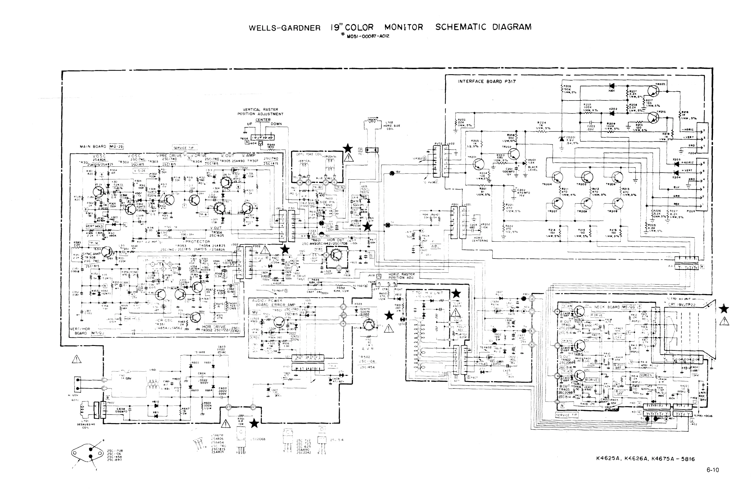
This page is a drawing, shown as the original scan.
VERT/HOR BOARD (MT/QJ)
| Ref. No. | Part No. | Description | Rel. No. | Part No. | Description |
RESISTORS CAPACITORS (CONT.}
| R301 | 203X6500-628 | 820 Ohm, | 118W Carbon | 6313 | 203X0025-087 | 47 uF, SOV Electrolytic | |
| F302 | 203X6500-902 | 12k Ohm, | 118W Carbon | 315 | 203X0015-082 | 10 uF, 25V Electrolytic | |
| F303 | 203X6500-927 | 15k Ohm, | 418W Carbon | C316 | 203X1100-220 | 3300 uF, 50V, + 10% | Mylar |
| R304 | 203X6500-886 | 10k Ohm, | 1/8W Carbon | 317 | 202X8000-616 | 100 pF, 50V, + 10% Ceramic | |
| R305 | 203X6501-241 | 330k Ohm, + 5%, | VW Carbon | 351 | 202X7000-281 | 1500 pF, 50V, + 10% Ceramic | |
| F306 | 203X6500-645 | 1k Ohm, # 5%, 18W Carbon | C352 | 202X7000-247 | 1000 pF, 50V, + 10% Ceramic | ||
| F307 | 203X6500-689 | 1.5k Ohm, + 5%, VW Carbon | C353 | 203X1100-573 | 0.022 uF, 50V, + 10% | Mylar | |
| R309 | 203X6500-724 | 2.2k Ohm, * 5%, VW Carbon | 355 | 203X1100-858 | 0.1 uF, 50V, = 10% Mylar | ||
| R310 | 203X6501.285 | 470k Ohm, + 5%, 1/8W Carbon | 6356 | 203X0015-105 | 47 uF, 25V Electrolytic | ||
| R311 | 203X6501.065 | 56k Ohm, + 5%, | 1/8W Carbon | 6357 | 203X1201-013, | 0.015uF, 200V 10% PP | |
| R312 | 203X6501-126 | 100k Ohm, = | ir8W Carbon | C358 | 203X1201.034 | 0.018 uF, 200V, + 10% PP | |
| F313, | 203X6901-326 | 10k Ohm, * 5%, 1/8W Carbon | 359 | 203X0040-.013 | 47 uF, 160V Electrolytic | ||
| R314 | 203x6501-044 | 47% Ohm, | C360 | 202X7000-482 | 0.01 uF, 50V, + 10% Ceramic | ||
| A315 | 203X6500-628 | 820 Ohm, * 5%, 1/8W Carbon | 6361 | 203X1100-509 | 0.015 vF-50V, + 10% Mylar | ||
| F316 | 203x6500-420 | 120 Ohm, * 5%, 1/8W Carbon | 362 | 203X0025-058 | 10 uF, SOV Electrolytic | ||
| R317 | 203X6206-441 | 2.2 Ohm, # 5%, 1/2W Carbon | C363 | 203X 1205-487 | 0.07 uF, 630V, + 10% PP | ||
| F319 | 203X6500-169, | 100 Ohm, + 5%, | 1/8W Carbon | C364 | 202X7006-482 | 001 uF, 50V, ‘t 10% Ceramic | |
| 320 | 203X6500-927 | 15k Ohi, = 5%, | 1/8W Carbon | ||||
| F321 | 203X6700-509 | 560 Ohm, + 5 | |||||
| R322 | 203X9100-121 | 22 Ohm, + 5%, | SEMICONDUCTORS | ||||
| F323 | 203X6500-689 | 1.5K Ohm, £5 | |||||
| R324 | 203X6500-988 | 27k Ohm, * 5%, 1/8W Carbon | TR301 | 200X4082-614 | Transistor, 2548260 | ||
| R325 | 203X6500-326 | 47 Ohm, * 5%, 1/8W Carbon | TR302 | 200X3174-006 | Transistor, 28617400 | ||
| R328 | 203X6500-628 | 820 Ohm, = 5%, | /8W Carbon | TR303 | 200X3174-006 | Transistor, 25417400 | |
| A330 | 203X6500-886 | 10k Ohm, + 5%, | 1/8W Carbon | TR304 | 200X3174-006 | Transistor, 25017400 | |
| R331 | 203X6501:209 | 220k Ohm, + 5%, | 1/8W Carbon | R305 | 200X4049-081 | Transistor, 2SA490YLBGLI | |
| R351 | 203X6500-724 | 2.2k Ohm, = 5%, 1/8W Carton | TR306 | 200X3162538 | Transistor, 2SC1625YLBGLI | ||
| R352 | 203X6500-927 | 15k Ohm, + 5%, | 1/8W Carbon | R307 | 200X3 174.014 | Transistor, 28C1740R | |
| R353, | 203X6500-944 | 18k Ohm, + 5%, V/8W Carbon | TR308 | 200X3174-006 | Transistor, 25C1740 | ||
| R354 | 203X6500-783, | 3.9k Ohm, & 5%, 1/8W Carbon | TR351 | 200X4085-415, | Transistor, 2SA854Q | ||
| F355 | 203X6500.902 | 12k Ohm, + 5%, 1/8W Carbon | R352 | 200X3172-208 | Transistor, 25C1722BKS | ||
| F356 | 203X6500-561 | 470 Ohm, + 5%, 18W Carbon | TR353 | 200X3174-006 | Transistor, 2561740 | ||
| R357 | 203X6500-724 | 2.2k Ohm, 2 5%, 1/8W Carbon | TR354 | 200X4082.614 | Transistor, 2SA826Q | ||
| R358 | 203X6500-666 | 1.2k Ohm, # 5%, 1/8W Carbon | x301 | 201X2010-144 | Diode, (St) 182473-T72 | ||
| R359 | 203X6501-088 | 68k Ohm, + 5%, 1/8W Carbon | x302 | 201X2010-144 | Diode, (St) 1$2473-172 | ||
| F360 | 203X5500-471 | 27 Ghm, + 5%, V/4W Comp. | x303 | 200X8000-025 | Diode, (GE), INSOTVGL | ||
| R361 | 203X6000-998 | 1.2k Ohm, | 5%, | 1/8W Carbon | x304 | 200X8010-165 | Diode (S1) 1S581 |
| R363 | 203X6500-666 | 1.2k Ohm, + 5%, 1/8W Carbon | X305 | 201X2010-165 | Diode ($1) 1SS81 | ||
| R364 | 203X9014-988 | 47k Ohm, = 5%, 1W MO. | X306 | 201X2010-165 | Diode (SI) IS$81 | ||
| R365, | 203X6700-989 | 56k Ohm, = 5%, /2W Carbon | x307 | 200X8010-102 | Diode (Si) MAZ6W | ||
| A366 | 203X6001-148 | 3.3k Ohm, + 5%, 1/8W Carbon | X308 | 200X8010.094 | Diode (St) 182473 | ||
| F367 | 340X2222734 | 2.2k Ohm, = 5%, 1/2W Carbon | x351 | 201X2010-144 | Diode (SI) 1$2473-T72 | ||
| R368 | 203x6500-785 | 39k Ohm, * 5%, 1/8W Carbon | X32 | 201X2010-144 | Diode (SI) 182473-172 | ||
| R369 | 203X6500-762 | 3.3k Ohm, + 5%, /4W Carbon | X353 | 201X2010-144 | Diode (St) 1S2473-172 | ||
| F370 | 302X6 100-961 | 1k Ohm, * 5%, 1/4W Carbon | X354 | 201X2010-144 | Diode (Si) 182473-172 | ||
| R371 | 203X6104-751 | 2.7k Ohm, + 5%, | 1/4W Carbon | X355, | 2008220-851 | Diode (Zener) RD10EBI | |
| R301 | 204X2122.093 | Varistor, 250K Ohm, Vert, Hold | X366 | 200X8100-130 | Diode (HS) AU-1 0.3 US | ||
| vR302 | 204X2114-065 | Varistor, 20K Ohm, Vert. Size | |||||
| R351 | 204X2114-059 | Varistor, 50K Ohm, Hor. Hotd | . |
MISCELLANEOUS
| CAPACITORS | 9301 | 204X9300-958 | Socket, 6 Pin | |||
| 15 | uF, SOV, + 10% Mylar | 9302 | 204X9300.958 | Socket, 6 Pin | ||
| CaP | 300K1900573 | 8022 uF. 50v. | 90% Myer | P01 | 204X9601-195 | Plug, 6 Pin |
| C304 | 203X1100-858 | 0.1 uF, SOV, + 10% Mylar | P302 | 204X9601-195 | Plug, 6 Pin | |
| 306 | 203x0025-026 | 2.2 uF, 50V, Electrolytic | TH301 | 201X0000-534 | Thermistor | |
| 307 | 203X 1100-928 | 0.15 uF, SOV, + 10% | Mylar | |||
| 309 | 203X1100-858 | 0.1 uF, 50V, + 10% Mylar | ||||
| €310 | 203x0010011 | 22 uF, 16V Electrolytic | TRANSFORMERS & COILS | |||
| cat | 203X0020-099 | 1000 uF, 35V Electrolytic | ||||
| e312 | 202X7000-469 | 0.0082 uF, 50V, + 10% Ceramic | usst | 201X5200-091 | Coll, Horlz. Osc. |
POWER BOARD (MV)
| 503 | 203x0010-011 | 22 UF, 16V Electrolytic | |||
| RESISTORS | 551 | 203X0005-046 | 220 uF, 10V Electrolytic | ||
| sor | 204%1725-052 | 180 Ohm, + 10%, | 15W WW | SE | ND |
| 50 | 203X6000-608 | 100 Ohm, + 5%, | /8W Carbon | ||
| F503 | 203X6000-960 | 1k Ohm, ‘ 5%, 1/8W Carbon | MICONDUCTORS | ||
| R504 | 203X6000-879 | 560 Ohm, * 5%, 1/8W Carbon | R501 | 200X3174-006 | Transistor, 2561740 |
| R505 | 203X9014-965 | 39k Ohm, + 5%, 1W M.O. | Ate TR502 | 200X3145-404 | Transistor, 2501454 |
| R506 | 203X6500-842 | 6.8k Ohm, + 5%, 1/8W Carbon | R551 | 200X3172-305 | Transistor, 251723 |
| R551 | 203X6500-420 | ) | X501 | 201X2230-042 | Diode, (S!j Zener EQB01-06V |
| R501 | 204X2050-001 | Varistor Vert. Adj. | xs02 | 201X2010-144 | Diode, (SI) 182473-172 |
CAPACITORS MISCELLANEOUS
| 501 | 203X0040-020 | 10 uF, 160V Electrolytic | 501 | 204X9300-958 | Socket, 6 Pin |
| C502 | 202X7000-281 | 1500 pF, S0V, + 10% Ceramic | P501 | 204X9601-195 | Plug, 6 Pin |
| TH501 | 207X0000-618 | Thermistor |
6-11
NECK BOARD (MS/QG)
| Ref. No. | Part No. | Description | Ret. No. | Part No. | Description |
RESISTORS
| Raat | pocermeled | akon 2 oe TN Geer | C403 | 202X7000-247 | 1000 pF, S0V, 10% Ceramic | |
| ; | 4 | C404 | 202x7110-019 | 1500 pF, 2kV' = 10% Ceramic | ||
| R403 | 203x6500-709 | 18k Ohm + 5% 1/8W Carbon | ||||
| a | DoaKes00-447 | te0 Ohm a 6% (EW Carbon | C405 | 202X7150.018 | 100 pF, 12kV, + 10% Ceramic | |
| ned | Soaxesoouad | 220 Ohm 2 8% | BW Carbon | C408 | 202X7050-483, | 01 UF, 500V,' + 10% Ceramic |
| ‘ | C407 | 202x7110.019 | 4800 pF, 2kV + 10% Ceramic | |||
| R406 | 203X6500-447 | 150 Ohm + 5% | 18W Carbon | |||
| C408 | 202X8000-550 | 68 pF, 50V, + 10% Ceramic | ||||
| R407 | 203X6500-508 | 270 Ohm + 5% | 1/8W Carbon | |||
| R408 | 203X6500-508 | 270 Ohm + 5% | 18W Carbon | C409 | pean | 68 pF, SOV, + 10% Ceramic |
| R409 | 203X6500-800 | 4.7k Ohm | 5% 1/8W Carbon | ca10 | 202X8000-550 | 88 pF, 50V, + 10% Ceramic |
| Ra10 | 203X6500-800 | 4.7k Ohm + | 5% 1/8W Carbon | |||
| Ratt | 203X6500-800 | 4.7k Ohm + 5% 1/8W Carbon | ||||
| Rat2 | 203x9104-809 | 12k Ohm + 5% 2.0W Metal Oxide | ||||
| Ra13 | 203X9104-809 | 12k Ohm 3 5% 2.0W Metal Oxide | SEMICONDUCTORS | |||
| Rata | 203X9104-809 | 12k Ohm & 5% 2.0W Metal Oxide | ||||
| Ra15 | 203X5601-313 | 2.7k Ohm & 10% 1/2W Comp. | TRAO1 | 200X3206-800 | Transistor, 2802068, 28C1514 | |
| Ra16 | 203X5601-313, | 2.7k Ohm + 10% 1/2W Comp. | (R output) | |||
| Ra17 | 208%5601-313 | TR402 | 200X3206-800 | Transistor, 2SC2088, 26C1514 | ||
| R418 | 203X5602.254 | 470k Ohm + 10% 1/2W Comp. | (G outpur, | |||
| aig | 203X5602-185 | 330k Onm + 10% 1/2W Comp. | ||||
| Razz | 203X9105-117 | 1.0 Ohm + 10% 2W Metal Oxide | T4038 | es | Raina | eco |
| R423 | 203X5102-155 | 270k Ohm + 5% t/4W Carbon | ; | |||
| vRaot | 204X2115-014 | 500 Ohm Varistor R Drive | “ | peetared | Bicae lessen teen | |
| R402 | 204x2115-014 | 500 Ohm Varistor 8 Drive | ae | 201%2100-126 | Bigot tesoer ace | |
| VR403 | 204X2115-006 | 5k Ohm Varistor R Cutoff | ‘01X2100- | iode, | (protector) | |
| vR404 | 204X2 115-006 | 5k Ohm Varistor G Cutoff | ||||
| R405 | 204X2115-006 | 5k Ohm Varistor B Cutoff | ||||
| VRA06 | 204x2000-025 | 1M Ohm Varistor Screen | MISCELLANEOUS | |||
| CAPACITORS | 1401 | 208X5003-729 | Socket, 5 Pin | |||
| 402 | 206X5003-983 | Socket, 3 Pin | ||||
| e401 | 202%7000-247 | 1000 pF, 50V, 10% Ceramic | P401 | 204X9600-329 | Plug, 5 Pin | |
| C402 | 202X7000-247 | 1000 pF, 50V, 10% Ceramic | Paoz | 204x9600-254 | Plug, 3 Pin |
ak 297X2000-072 HIGH VOLTAGE ASSEMBLY (1701)
AxR701 R702 x701 x702 X703
C201 FINAL ASSEMBLY PARTS
| 204X 1625-058 | 3.3 Ohm, + 10% 10W WW Resistor | 4. 88x.0129-506 | J9VITP22 Pix Tube |
| 204X3901-125 | Focus Control | 38 5554-000 | Assy. Purity Shid/Degaussing |
| Diode (SI HV) | 205X9800-256 | Lateral/Purity Assembly | |
| Diode (SI HV) & Part of T701 | A | 202X1110-810 | Yoke, Deflection |
| Diode (S! HV) | 208X2000-946 | CRT Socket |
2972000072 HV Unit (1701) 6A0397 Plug, Line Cord 9A2753-003 Degaussing Coil (L701)
INTERFACE BOARD (P305) (MODEL 19K4606)
RESISTORS SEMICONDUCTORS
| 340x3910-934 | 91 Ohm, 5%, 1!2W Carbon | TR201 | 86x0121-001 | Transistor (NPN) |
| 340X3102-934 | 1k Ohm, 5%, 1/2W Carbon | TR202 | 86X0121-001 | Transistor (NPN) |
| 340X2101-934 | |. 4W Carbon | TR203 | 86X0121-001 | Transistor (NPN) |
| 340X3331-944 | 1/2W Carbon | TR204 | 86X0066-001 | Transistor (PNP) |
| 340X3102-934 | f, 12W Carbon | TR205 | 86X0066-001 | Transistor (PNP) |
| 3402152934 | 1/4W Carbon | TR206 | 86X0066-001 | Transistor (PNP) |
| 340X2101-934 | 4W Carbon | TR207 | 86X0121-001 | Transistor (NNP) |
| 340X3102-934 | W2W Carbon | TR208 | 86X0121-001 | Transistor (NPN) |
| 340X2331-934 | 114W Carbon | TR209 | 86X0121-001 | Transistor (NPN) |
| 340X2331-934 | 1/4W Carbon | zp201 | 66x0040-018 | Diode, Zener, 6.8v, 5%, 0.5W |
| 340X2331-934 | 1/4W Carbon | 20202 | 66x0040-019 | Diode, Zener, 3.9v, 5%, 0.5W |
340X2201.934 200 Ohm, 5%, 1/4W Carbon
| 340X2201-934 | 200 Ohm, 5%, | 1/4W Carbon |
340X2201.934 200 Ohm, 5%, 1/4W Carbon MISCELLANEOUS 40X0590-017 1.5k Ohm, Black Level Contro!
| J201 | 204X9300-958 | Socket, 6 Pin | ||
| 4202 | 204X9300-958 | Socket, 6 Pin | ||
| CAPACITORS. | 4203 | 206X5019-207 | Socket, 4 Pin | |
| 201 | 204X9601-195, | Plug, 6 Pin | ||
| 45X0524.038 | 1000 uF, 16V Electrolytic | 202 | 204X9601-195 | Plug, 6 Pin |
| P203 | 204X9600-845 | Plug, 4 Pin | ||
| P205, | 6A0393-006 | Plug, 6 Pin |
6-12
Blue ontex Rep XI01.XIO3 and XI05 VIDEO AMP, 25C454C omguno X102.xI04 and XI06 VIDEO AMP. 25A673C
fj ______j __ | i 1301x308 1300x808 ISYNe. AMP S8ca8eC or ANCI605
X309 BEAM LIMITER 2SA673 X304 BLANKING 28C4S4C or abies ayo eu
pea assy | lerr soceer |
X901 POWER DRIVE 252688 X 902 ERROR AMP 2SC7890 |
28ci106a, asciasa / BOWER REGULATOR ran,, N ra i
Kc aaae > tot 2800 Re On ise
SU-11334 MAIN PCB ASSY yee, ae Ea
| aut oe, 250820
00-4147-04 G07-CBO
6-13 Schematic Notes Unless otherwise specified Resistance: (2) (K*KQ, MM}, 1/4 (W) carbon resistor Capacitance: 1 or higher-» (pF), less than 1 (yF) working voltage -» 50 (V) ceramic capacitor Inductance: (H) Electrolytic Cap: Capacitance Value (vy F)/working voltage (V), NP — non-polar (or bipolar) electrolytic cap. Refer to the parts list for additional component information.
2 indicates test point connection
- indicates chassis ground unless otherwise specified
Hz indicates cycles per second
For safety purposes (and continuing reliability) a replace all components marked with safety syrnbol with identical type.
Parts identification on circuit boards: e.g. SU1126A (R107 = R1107) SU3030A (R113 = R3113)
REPLACEMENT PARTS LIST - ELECTROHOME 19”’ MONITOR
Components identified by the A symbol in the PARTS LIST and on the Schematic have special characteristics important to safety. DO NOT degrade the safety of the set through improper servicing.
Abbreviations for Resistors and Capacitors
Resistor Capacitor
| CR | : Carbon Resistor | Cc Cap. |
| Comp. R | : Composition Resistor | M Cap. |
| OM R | : Oxide Metal Film Resistor | E Cap. |
| VR | : Variable Resistor | BP E Cap. |
MF R : Metal Fiim Resistor
| CMF R | : Coating Metal Film Resistor | MM Cap. |
| UNF R | : Nonflammabie Resistor | PP Cap. |
| FR | : Fusible Resistor | MPP Cap. |
PS Cap
Tan. Cap. : Ceramic Capacitor Mylar Capacitor
Electrolytic Capacitor Metalized Mylar Capacitor Polypropylene Capacitor
Bi-Polar (or Non-Polar)
: Metalized PP Capacitor Polystyrol Capacitor : Tantal Capacitor
SERVICE REPLACEMENT PARTS LIST
Symbol Description Main P.C.B. Ass'y CRT Socket P.C.B. Ass'y Purity Shield Ass’y
6-14 Part Number SU-1133A SU-3032A, 07-220083-03
Outside of the P.C.B. Ass’y Symbol Description Picture Tube 19” A AdDeflection Yoke PC Magnet A AsFlyback Transf. A ASHVR ROS UNF Resistor 220Q,25W K C04 C Capacitor 150pF, AC1.5KV X01 Si. Transistor x02 Si. Transistor sc Screw #8-% sc Screw % x % Pix Tube Mtg. (4) WA Pyramidal Lock Washer (4) Nut Retainer, Pix Tube Mtg. (4) Clip — P.C.B. Support Standoff Wire Terminal (Gnd. Strap) Terminal Lug (Gnd.) Groundstrap Assy. Grounding Spring Wire Hook (Gnd. Strap) Purity Shield Holddown Clamp Support Brkt. RH Support Brkt. LH Chassis Base Yoke Wedge (3)
Purity Shield Ass’y. Parts List
Symbol Description Degaussing Coil D911, D912 Rectifier 1 Amp 600V (2) Pin Terminal (2)
Purity Shield (2 pes.) Purity Shield (2 pcs.) Ccst1 Capacitor 100nF 10% 400V R921 Resistor, Wirewound 3302, 4W Fire Retardent Term. Strip 4 Lug
CRT Socket P.C.B. Ass’y (SU-3032A) Parts List
Resistors Symbot Description
| R3105 | Vv | R 200 |
| R3106 | Vv | R 200 |
| R3113 | v | R 5K |
| R3114 | v | R 5K |
| R3115 | Vv | R 5« |
| R3116 | OM | R 10KQ2W J |
| R3117 | OM | R 10KQ2W J |
| R3118 | OM | R 10KQ2W J |
R3119 Comp. R 3.3KQ’%W K R3120 Comp. R 3.3KQ*WK C3121 Comp. R 3.3KQ2%WK
Capacitors Symbol Description C3107 E Cap. 10uF 250VA C3108 C Cap. 100CpF DC1400V P
Coils Symbol! Description L3101 Peaking Coil
6-15 Part Number 17-7198-03 A29779-D = 21-141-01 A75034-B = 29-32-01 A29951-B A46600-A QRF258K-221 QCZ0101-005 2SD870 28C1106A 31-610818-06 31-601418-12 33-255-01 33-494-01 33-629-02 33-670-010R-02 34-228-03 34-33-04 34-574-02 35-212-03 35-3053-02 35-2348-01 35-3890-01 35-3890-02 38-449-02 39-1233-01
Part Number 21-1007-30 28-22-27 34-708-01 34-709-01 35-3847-01 35-3847-02 48-171544-62 42-113301-03 34-492-09
Part Number QVZ3234-022 QVZ3234-022 QVZ3234-053 QVZ3234-053 QVZ3234-053 QRG029J-103 QRGO29J-103 QRG029J-103 QRZ0039-332 QRZ0039-332 QRZ0039-332
Part Number QEWS53EA-106 QCZ9001-102M
Part Number QQL043K-101
Semiconductors Symbol X3101 X3102 X3103
Miscellaneous Symbol A Description Si. Transistor Si. Transistor Si. Transistor
Description ASCRT Socket
Main PCB Ass’y (SU-1133A) Parts List
Resistors Symbol A1406 R1408 Ri410 R144 R1415, R1421 R1422 ASFR1401 AR1503 Ri504 R1509 R1512 R1514 RI515 R1522 R1523, R1528 R1534 VR1501 4sR1703 ANRI704 4SR1901 R1902 R1903 R1904 R1905 401908 AR1909 R1910 ANFR1901
Capacitors Symbol C1301 1402 1407
C1412 1508 AC1512 AC1513 ACI1514 C1515 C1520 C1523 C1524 Acis3t AC1532 C1904 C1905 Description Vv Vv CMF OM OM OM v AF ASCMF
2SCMF AsPosistor UNF CMF OM Om ASCMF Vv 2SCMF AF DODDUDDHDD ODHVVDVVUVDVVVUVIVHVIVID 2002 2002 6.8QAW JS 3.3K Q1W J 27K QIW J 12KQ2W J 10KQ. 68Q2W K 11.BKQ AW +1% SKQ 10K 22W J 8.2KQ2W J 82022W J B.201W J 4.721W J 68 22W J 3902Q1W J
39Q AW + 1% 7.68KQ.UW +1%
2Q7W K 4.723W J 10KQ2W J WKQIW JS 47 QW +1% 2K 2.74K QW +1% 2202%W K
Description BPE Tan. E E E PP Ape APP App PP BPE E M Ape A\PP E E Cap. Cap. Cap. Cap. Cap. Cap. Cap. Cap. Cap. Cap. Cap. Cap. Cap. Cap. Cap. . 3.3uF 50V A . 2.2UuF 16V K 4.7uF 6.3V A 100uF 160V A 3.3uF 160V A 5600uF SOV J 2000pF DC1500V J 2000pF DC1S00V J 2000pF DC1500V J O.53uF DC1200V J 3.3uF SOV A tuF 160V A 0.tuF 200V K 2000pF DC1500V J 1500pF DC1500V J Cap. Cap. 10UF 250V A
6-16 Pari Number 2SC1514VC 28C1514VC 28C1514VC
Part Number A76068
Part Number QVZ3230-002 QVZ3230-002 QRX019J-6R8 QRGO019J-332 QRGO019J-272 QRGO26J-1232 QVZ3230-014 QRHO024K-680M QRV142F-1182 QVZ3230-053 QRGO26J-103Z QRG026J-822Z QRG026J-821Z QRX019J-8R2 QRXO19J-4R7 QRG026J-6802 QRGO19J-391 ERZ-C0SZK471 ERZ-CO5DK271 QRV122F-3902 QRV142F-7681 A75414 QRFO76K-2RO QRX039J-4R7 QRGO26J- 1032, QRGO19J-183 QRV122F-470Z QVPSA0B-023E QRV142F-2741 QRH124K-221M
Part Number QEN61HA-335Z QEES1CK-225B QEW515A-475 QEWS52CA-107 QEW52CA-335 QFP31HJ-562 QFZ0082-202 QFZ0082-202 QFZ0082-202 QFZ0067-534 QEN61HA-335Z QEW62CA-105Z QFM720K-104M QFZ0082-202 QFZ0082-152 QEY0034-001 QEWS52EA-106
Coils Symbol 11502 L1503 L1504
Transformers Symbol T1501 T1503
Semiconductors Symboi 101501
X1101 X1102 X1103 X1104 X1105 X1106 X1301 X1302 X1303 X1304 X1305 X1401 X1402 X1501 X1901 X1902
D1101 D1102 D1103 D1301 D1401 D1402
D1503 D1504 D1505 D1506 D1507 D1508 41701 A\D1901 A\D1902 A\D1903 AXD1904 A\D1905
Miscellaneous Symbol AXF1901 AXF1902
Description Part Number
Linarity Coil A39835 Width Coil €30380-A Heater Choke C30445-A
Hor. Drive Transf. A46022-BM Side Pin Transf. C39050-A
IC HA11244
Si. Transistor 2SC1685(R) Si. Transistor 2SA673(C) Si. Transistor 28C 1685(R) Si. Transistor 2SA673(C) Si. Transistor 2SC1685(R) Si. Transistor 2SA673(C) Si. Transistor 2SC1685(R) Si. Transistor 2SC1685(R} Si. Transistor 2SA673(C) Si. Transistor 2SC1685(R) Si. Transistor 2SC1685(R) Si. Transistor 28D478 Si. Transistor 2SD478 Si. Transistor 2SC2610BK Si. Transistor Si. Transistor
Si. Diode Si. Diode Si. Diode Si. Diode Si. Diode Zener Diode
Si. Diode Si. Diode Zener Diode Si. Diode Si. Diode Si. Diode AZener Diode ASi. Diode ASi. Diode ASi. Diode ASi. Diode AdZener Diode
Description AFuse 1.25 ANUL Fuse 3A 2SC2688 (K.L.M.) 2SC1890A (E-F.) WosA WO6A WO6A 1$Z473H 18Z473H RD10F(C) HF-1 VO9E RD1iE(B) WO6A 18S81 18Z473H RD20EV2 181887 181887A 181887 181887A RO6.8EV3
Part Number QMF53U1-1R25S QMF66U1-3ROS
6-17
X01, x}O3 and XIOS VIDEO AMP, 2SC454C oy 25C1685. xi02.x108 and XI06 VIDEO AMP. 25a673C os
i i | x301 ] x30a | ae aay [PS | | R31¢ 4 tok | L
- 302 ,.X305,X306 sm ; 2ieasac or 25c1685
tou tise v svne | To yao geaw tuaren osae7s Pts 304 BLANKING T BA) Relese bos dee 1303, xsoay 88 oS
! Mio xiSS Ae VIDEO CUTPUT 25c26i or B8cisiav
1COl POWER REGULATOR sraees SU-I103A MAIN PCB ASSY
xa02 oe x401, x402 H 250478
& Sots byor DEFLECTION YOKE
aa Fi Yeo nPaVE Xo navr oe Beagee wes BEelsBPE, escosrw 35882 LL. sen Vo Vice weaves 28C26ii or B8C26i0BK 250869 a fe Oo) 8h coe acigoy conrsonr
G07-FBO
00-4147-03 Scnematic Notes Unless otherwise specified Resistance: (2) (K*KQ, M-MQ), 1/4 (W) carbon resistor Capacitance: 1 or higher-» (pF), less than 1—> (yF) working voltage -» 50 (V) ceramic capacitor inductance: (v H) Electrolytic Cap: Capacitance Value ( F)/working voltage (V), NP — non-polar (or bipolar) electrolytic cap. Refer to the parts list for additional component information. 2 indicates test point connection ah indicates chassis ground unless otherwise specified Hz indicates cycles per second
For safety purposes (and continuing reliability) Aa replace all components marked with safety symbol with identical type.
Parts identification on circuit boards: e.g. SU1126A (R107 = R1107) SU3030A (R113 = R3113)
REPLACEMENT PARTS LIST - ELECTROHOME 13” MONITOR
Components identified by the A symbol in the PARTS LIST and on the Schematic have special characteristics important to safety. DO NOT degrade the safety of the set through improper servicing.
Abbreviations for Resistors and Capacitors
Resistor Capacitor
| CR | : Carbon Resistor | C Cap. |
| Comp. R | : Composition Resistor | M Cap |
| OMR | : Oxide Metal Film Resistor | — Cap. |
| VR | : Variable Resistor | BP E Cap. |
MFR : Metal Film Resistor CMFR Coating Metal Film Resistor MM Cap.
| UNF R | : Nonflammabie Resistor | PP Cap. |
| FR | : Fusible Resistor | MPP Cap. |
PS Cap Tan. Cap. : Ceramic Capacitor Mylar Capacitor : Electrolytic Capacitor Bi-Polar (or Non-Polar) Electrolytic Capacitor : Metalized Mylar Capacitor Polypropylene Capacitor : Metalized PP Capacitor Polystyro! Capacitor : Tantal Capacitor
Symbol
Outside of the P.C.B. Ass’y Symbol Avo1 Apyo1
ARI AROS Aco4 x01 1C01 Lot
BR BR sc WA
CH Description Main P.C.B. Ass'y CRT Socket P.C.B. Ass’y
Description A’Picture Tube A\Deflection Yoke PC Magnet Wedge Flyback Transf. AsFocus V R UNF Resistor 2202, 25W. K ANC Capacitor 150 pF, AC1.5KV Si, Transistor 1C Regulator Degausing Coil Degausing Coil Pin Terminal (2) Degausing Coil Pin Terminal Housing Groundstrap Ass’y. Groundstrap Wire Terminal Groundstrap Spring (2) Support Bracket RH Support Bracket LH SCREW 10-% Pix Tube Mtg. (4) Pyramidal Lockwasher (4) Clip P.C.B. Support (2) Ground Lug Chassis Base
6-19 Part Number SU-1103A SU-3016A
Part Number 370ESB22(E) 29123-V A76366-A, 30006 A19183-A A46606-A QRF258K-221 QCZ0101-005 2SD869 STR383 21-1007-31 34-708-01 34-709-01 34-697-04 34-228-03 35-3560-01 35-3919-01 35-3919-02 31-631018-08 33-255-01 33-629-02 34-33-04 38-452-01
Main P.C.B. Ass'y (SU-1103A) Parts List
Resistors Symbol R1406 R1408 R1410 R1414 R1I415 Ri421 R1422 A\FR1401 AXR1503 R1504 R1509 R1511 R1514 R1515 R1522 R1523 R1528 R1534, VR1501 A\R1703 2R1704 ASR1901 R1902 R1903 R1904 ASFR1901 Capacitors Symboi C1402 C1411 C1412 C1508 C1511 AC1512 AC1513 AC1514 C1515 ©1520 C1524 1904 1905 AC 1907
Colls Symbol L1501 L1502 L1503 L1504 L1901
Transformers Symbol T1501 T1503 Description v Vv R R CMF R OM R OM R OM R Vv AF R R ASCMF R v R OM R OM R OM R CMF R CMF R OM R OM R ZN ZN R R A\CMF R AXCMF R A’Posistor UNF R CMF R OM R AF R 2002 2002. 6.8Q1W J 3.3KQ 1W J 2.7KQ1W J 12KQ2W J 10KQ 6822W K 11.8KQUW +1% 5KQ. 1OKQ2W J 5.6KQ.2W J 6802 2W J 8.2Q1W J 4.701W J 56 Q2W J 3902 1W J
39K QW +1% 7.68K QYW +1%
2Q7W K 5.623W J 1OKQ2W J 2202 %W K
Description Tan. Cap. Cap. Cap. Cap. Cap. Cap. Cap. Cap. Cap. BPE Cap. Cap. E E PP E ANPP AspP AspP PP
M E E 2.2uF 16V K 100uF 160V A 3.3uF 160V A 5600pF 50V J 47TuF 160V A 2000pF DC1500V J 2000pF DC1500V J 2500pF DC1500V J 0.53uF DC1200V K 1uF 50V A Q.1UF 200V K Cap. Cap. A\MM Cap. 10uF 250V A . 0.1UF ACI50V Z
Description Peaking Coil Liniarty Coil Width Coil Heater Choke Line Filter
Description Hor. Drive Transf. Side Pin Transf.
6-20 Part Number QVZ3230-022 QVZ3230-022 QRX019J-6R8 QRG019J-332 QRG019J-272 QRG029J-123 QVZ3224-014H QRHO24K-680M QRV142F-1182 QVZ3230-053 QRGO029J-103 QRGO29J-562 QRG029J-681 QRX019J-8R2 QRX0195-4R7 ORGO29J-560 ORGO019J-391 ERZ-C05ZK471 ERZ-C05DK271 QRV122F-3902 QRV142F-7681 AT5414 QRFO76K-2RO QRX039J-5R6 QRGO26J-103Z QRH124K-221M
Part Number QEES51CK-225B QEW52CA-107 QEW52CA-335 QFP31HJ-562 QEWS52CA-476S, QFZ0082-202 QFZ0082-202 QFZ0082-252 QFZ0067-534 QEN61HA-105Z QFM72DK-682M QEY0034-001 QEWS2EA-106 QFZ9008-104
Part Number A75360-6 A39934 30380-A 30333-A A39475-J
Part Number A46022-BM C39050-A
Semiconductors Symbol (C1501
x1101 x1102 X1103 X1104 X1105 X1106 x1301 x1302 X1303 x1304 X1305 x1401 x1402 X1501 X1701 D1101 D1102 01103 01301 01401 01402 D1503 01504 01505 01506 01507 01508 401701 A\D1901 A\01902 A\01903 AxD1904
Miscellaneous Symbol ASF1901 A\F1902 Description Le.
Si. Si. Si. Si. Si. Si. Si. Si. Si. Si. Si. Si. Si. Si. Si. Si. Si. Si. Si. Si. Transistor Transistor Transistor Transistor Transistor Transistor Transistor Transistor Transistor Transistor Transistor Transistor Transistor Transistor Transistor Diode Diode Diode Diode Diode Zener Diode Si Si. |. Diode . Diode Zener Diode Si. Si Si . Diode |. Diode |. Diode AZener Diode ASi ASI. ASi ASi . Diode |. Diode . Diode . Diode
Description ZFuse 1A AXUL Fuse 3A
6-21 Part Number HA11244
2SC1685(R) 2SA673(C) 2SC1685(R) 2SA673(C) 2SC1685(R) 2SA673(C) 2SC1685(R) 2SC1685(R) 2SA673(C) 2SC1685(R) 2SC1685(R) 2SD478 2sp478 2SC2610BK 28C1685(P-S) Wo6A Wo6A Wo6A 182473H 182473H RD10F(C) HF-1 Vo9e RD11E(8) WO6A 18881 182473H RD20EV2 181887A 181887A 1818878 181887A
Part Number QMF53U1-1ROS QMF66U1-3R0S
CRT Socket P.C.B. Ass'y (SU-3016A) Parts List
Resistors Symbol R3105 R3106 R3113 R3114 R3115, R3116 R3117 R3118 R3119 R3120 R3121
Capacitors Symbol 3107 C3108
Colls Symbol 3101
Semiconductors Symbol X3101 X3102 X3103
Miscellaneous Symbol A Description 2002 2002 SKQ. 5KQ 5KQ IM 10K N2W J iM 10K N2W J OM R 10K22W J Comp. R 3.3K2%W K Comp. R 3.3KQ*%W K Comp. R 3.3KQ%WK oo<<<<< DDDDDDVD
Description € Cap. 10uF 250V A C Cap. 1000pF DC1400V P
Description Peaking coil
Description Si. Transistor Si. Transistor Si. Transistor
Description A\CRT Socket
6-22 Part Number QVZ3234-022 QVZ3234-022 QVZ3234-053 QVZ3234-053 QVZ3234-053 QRG029J-103 QRGO29J-103 QRGO29J-103 QRZ0039-332 QRZ0039-332 QRZ0039-332
Part Number QEWS2EA-106 QCZ9001-102M
Part Number QQL043K-101
Part Number 2802611 2SC2611 282611
Part Number A75522
VII. Coin Door Maintenance
SPECIAL NOTE: |f you have any questions about the coin acceptors in your game(s), please feel free to contact their manufacturers. Each manufacturer's name is PROMINENTLY imprinted on every acceptor mechanism. Metal mechanisms only: COIN MECHANISMS, INC. 817 Industrial Drive Elmhurst, IL 60126 Phone (312) 279-9150
COIN DOOR MAINTENANCE
METAL COIN ACCEPTOR MECHANISMS
Periodically, the metal coin acceptor mechanism(s) must be removed from the coin door and cleaned.
- Make sure the power to the game is off.
- Unlock and open the coin door.
TO REMOVE PUSH LATCHES DOWN
PLACE PEGS IN SLOTS TO REPLACE PULL MECHANISM OUT Metal and Plastic mechanisms: COINCO COIN ACCEPTORS, INC. 860 Eagle Drive Bensenville, IL 60106 Phone (312) 766-6781
. Remove the coin acceptor mechanism as shown in Figure 7-1. O Push down on the two spring loaded latches. O While holding the latches down, pull the top of the coin acceptor mechanism toward you. O Release the latches and lift out the coin acceptor mechanism.
PUSH MECHANISM IN
Figure 7-1 Removing and replacing coin acceptor
- Clean the magnet of al! foreign particles. See Figure 7-2. O This may be accomplished by swinging the gate open as shown in the above figure.
- Remove the cradles and undersize levers and clean the bushings. (A pipe cleaner makes a good bushing cleaner.) 2 Also clean the pivot pin.
- Whenever needed, the coin acceptor should be cleaned with hot water and cleanser in the following manner: ©] Place the coin acceptor in boiling water for about ten minutes. | CAUTION: BE CAREFUL NOT TO BURN YOUR- SELF.
G Next, use a brush and kitchen cleaner to remove all remaining foreign matter from the unit. O Rinse the coin acceptor in clean boiling water. O Dry the coin acceptor thoroughly by using filtered compressed air to blow it dry.
GATE OPEN AS SHOWN CLEAN MAGNET BY DRAGGING A SCREWDRIVER BLADE ACROSS SURFACE
Figure 7-2 Cleaning the metal coin acceptor
- To lubricate the coin acceptor: O Use ONLY powdered graphite and put it ONLY on the moving parts of the coin acceptor. These parts are called out in Figure 7-3. Be extremely careful to keep the powdered graphite away from paths that are traveled by the coins.
- WARNING — DO NOT USE OIL TO LUBRICATE THE COIN ACCEPTOR.
- Check the coin chute for obstructions such as: paper, gum, etc.
- Reinstall the coin acceptor to the coin door. See Figure 7-1. O Place the two pegs at the coin acceptors base into their retaining slots. O Now push the top of the coin acceptor toward the coin door until it snaps in place and is held there by the two spring loaded latches.
- Close and lock the coin door.
APPLY POWDERED GRAPHITE HERE
UNDERSIZE LEVER
CRADLE
Figure 7-3 Lubricating the metal coin acceptor
7-2
SQUEEZE PINS TOGETHER TO UNLOCK SWING BOTH GATES OPEN
HOLDING BOTH GATES TOGETHER, PUSH UP AND PULL OUT
Figure 7-4 Opening the plastic coin acceptor
PLASTIC COIN ACCEPTOR MECHANISMS The plastic coin acceptor mechanism(s) must be removed periodically from the coin door and cleaned.
- Make sure the power to the game is off.
- Unlock and open the coin door.
- Remove the coin acceptor mechanism(s) as shown in Figure 7-1. Push down on the two spring loaded latches. 0 While holding the latches down, pull the top of the acceptor mechanism toward you. CO Release the latches and lift out the mechanism.
- Squeeze the two pins indicated in Figure 7-4 together to open the mechanism and break it down into its three basic parts. O Clean the mechanism in hot soapy water. It never rusts. OD Rinse the mechanism in clean hot water and allow it to dry. O Reassermble the mechanism (it never needs lubrication).
- Check the coin chute for obstructions such as: paper, gum, etc.
- Reinstall the coin acceptor to the coin door. See Figure 7-5. O Place the two pegs at the coin acceptor’s base into their retaining slots. O Now push the top of the coin acceptor toward the coin door until it snaps in place and is held there by the two spring loaded latches.
- Close and lock the coin door.
ACCEPTOR CAN BE SET TO ACCEPT U.S. QUARTERS ONLY OR BOTH U.S. AND CANADIAN QUARTERS.
MAGNET
>
SLIDE MAGNET TO EXTREME RIGHT (AS. SHOWN) TO ACCEPT BOTH U.S. AND CANADIAN QUARTERS.
TO ACCEPT U.S. QUARTERS ONLY, SLIDE MAGNET TO EXTREME LEFT.
Figure 7-5 Changing the plastic coin acceptor to accept American or Canadian quarters.
MONITOR JACK
(essen
I-96 sromen 43 wl a4
- - (oat ores pon -4 | aia SEE S}7. i ; ; F 3 [sonatas to mon ths 7 7 F297 7 Soe ae rarer 1 (hn aoe Be A850 soe. ath —
cpu
! p i t 1 i
SOUND 1/0 BD,
TRON CT. *w-oorar-soos al 1 oo MOWAY MEG. Co, Ie W. BELMONT Ave FRANKLIN PARK, LL. 6013) = FINIMNED 5/10/82. Kemet
MONITOR Jack
POWER SUPPLY BD,
4 CPU BD
| Silas aa | ye | P08 | Soe Sante |
| sou | « | Nae! |
| i | : | Pal |
Seinen ee tae wou tae|
; m4 [eral . it m4 tad eo. 1 i _ mt} i i t
SOUND 1/0 BD.
-——,
7 UAL AMP BD.
sim 08 oo oar’ Low aa ve — { NOTESS Tee
| TRON UR." wos:coeee-soos | & gra corso ovar m, | . | . | oe | |
| Mow MES co, | seomee ea | © | = | Fa | |
| Be, a | we | : | a | ||
| PERRET RR A eo | = | = | on | wn | a |
msieo 12/88 me Keween
Furer SY
TRON MINI *wos-co729-1003
MOwAY MEG Co. (D601, BELMONT AVE, FRANKLIN’ PARK LL O13) FinsneD S702]82m-Keneps. NOTES? VIED GEN 80. NOU 90808 AS
CPU BO
i t _ i oo
SOUND 1/0 80,
ANGLE ENCODER
- “
This page carries no recoverable text. It is a drawing or a photograph. See the original scan.
This page carries no recoverable text. It is a drawing or a photograph. See the original scan.
MIDWAY MFG. CO.
DESIGNATION LIST
DESIGNATION.
cl,c2 c3,c4 c5,c6 C7-ClO CPI CP2,cP3
RILR2 R3,R4 R5-R8
u1,u2
Jl
J2
HSA1L2
MHI-MH4 DESCRIPTION
47 mf 25v rd.tant.
| 22mf | 6v '' | |! |
470mf 6v ax.elect. Amf 50v ax.cr 220mf 25v ax.elect. mf SOv axcr
2.7KN V4w 5% CRBN, 27H “ IQ Wew"' "
MB3730
RPiN STRT KKIS56
| 308 | 4 | " |
| 2" | “ | “ |
HEATSINK ASSY.
HEYCO BUSHING ni
\ J2 /
+ CPi
4apn_| [Sein] [4 em
wn &MED USED.ON KIC CRE]
HSA2 ~ wat
MH4 +
UNLESS OTHERWISE SPEC K DAN DATE SCALE CONCENTRICITY T.I.R. .. 002 Ti | [2-14-81 FULL FRACTIONAL . +1164 Foecnoa ware DECIMAL +005 HOLE DIA. +.002—.000 ANGLE +1/2° DO NOT SCALE DWG ELEC CHK FINISH CROSS REFERENCE LIST
DESCRIPTION QTY DESIGNATION PART NO.
| mf 50vaxcr | 6 | CALCIO | 0986-008001100 |
CP2CP3
| 47mf25vrdtant 2 | CIC2 | 0986-008003100 | ||
| 22mF By " | 2 | C3c4 | 0986-00800-1600 | |
| 220mf 25vaxclec, 1 | cP | 0986-00800-3200 | ||
| 470mf 6v | 2 | C56 | 0986-00800-1700 | |
| INAV 2w 5% | 4 | RS-RB | 0062-026D3-1XxXx | |
| 2701/4w | 2 | R3R4 | 0062 -068B3-1XXxX | |
| 27K" | 2 | RLR2 | 0062-199B3-1XxX | |
| MB3730 | 2 | U1,02 | 0066 -188x x - XX4x | |
| 2PINSTRTKKISG | 1 | v2 | 3000-16367 - 0200 | |
| 30 | "oo" | 2 | dly2 | 3000-16367 -0300 |
| aun | 1 | Jl | 3000-16367 -0400 | |
| HEATSINK ASSY, | 2 | HSAL, | 0986 - 00804-1800 |
HSA2
| HEYCO BUSHING | 4 MHI-MH4 | 0017-00042-0014 |
| PC BOARD | | | A080 - 90910-D000 |
MOS}: 00986-D010 THIS DWG. IS CONFIDENTIAL & PROPERTY OF MIDWAY MFG. CO.
MIDWAY MFG. CO. ABALLYCO. FRANKLIN PK., IL. 60131 REVISIONS DUAL PWR. AMP. ASSY [raarne: A0B2 -90910 - D000 1051-00986 -DO!IO
a 8 uw
on ©
a me —
i NC.
L. AUDIO
iL. SHIELD
KEY
V AUDIO RETURN
R. AUDIO
R. SHIELD
V AUDID
R—-
KEY
L+
N.C
te
| OK | ALT UF | 1 |
L : ai p> ————» L+
| > | EH | 6 | RS |
| 4| | 3730 | in jaw |
ul 5
| — | 2 | ———— Le | |||
| SHIELD | RS | + | Ay | ler | 2 a yaw |
| _ | | 27 | =c3 | | aS? | 8 log | |
| S| | aur | TT | |||
| ve | @v | | | j |
y —
\\ VAUDIO i
R+
+ rm TO CHIP'S
| [+ | cre | | crs |
7 =a. Vaupio > a
CPI 220urF
Vaunio > RETURN
DIM. TOLERANCES UNLESS OTHERWISE SPEC. CONCENTAICITY T.LR. FRACTIONAL DECIMAL + HOLE DIA. + .002— ANGLE DO NOT SCALE DWG 25V
| ao | a | 9 |
+ 1/64
| +1/2° Perec | or | FINISH |
THIS DWG. IS CONFIDENTIAL & PROPERTY OF MIDWAY MFG. CO.
MIDWAY MFG. CO. FRANKLIN PK., IL. 60131 A BALLY CO. oe DATE a 12-14-81 ATL
a DUAL PWR AMP
A082-90910-D000 REVISIONS PART NO. MO 5 |-00986- DOI!
DESIGNATION NO. DESCRIPTION
c lol
cP i cP 2 cP 3 cP4
cP 5 cP 6
R 101
R102
R103
R104
R105
R106
R107
R108
R109
RIO
Rijt
R112
OPTI
MH OPT IA
MH OPT IB
MH OPT 2A
MH OPT 2B
A080 - 91418-D000 4.7 uf TANT I6V RAD.
-Oluf 50V AX. CER. lOwf I6V AX. ELECT. -Ol wf 50V AX, CER -Ol wf 5OV AX. CER.
lOwf I6V AX. ELECT
Ol wf 50V AX. CER.
4.7K 1/4W 5%
4.7K 1/4W 5% 200K I/4W 5%
IM I/4W 5% 5SIK 1/4W 5%
120 ohm 1/4W 5% 91K 1/4w 5% 18K 1/4W 5% 200K 1/4W 5% iM 1/4W 5% 4.7K 1/4W 5% 5IK 1/4W 5%
OPB822S
74LS491
LM 339
10 PIN KK-156 TYP.
2 PIN KK-1I56 TYP.
5-40 SCREW
5-40 NUT
5-40 SCREW
5-40 NUT
P.C. BOARD 90% DESCRIPTION
-Oiwf 50V AX. CER.
4.7 wf I6V RAD. TANT. lOuf 16V AX. ELECT.
MH OPT IA,IB O)
Rie oT cPa 4 120 ohm 1/4W 5% 4.7K 1/4W 5% 18K I/4W 5%
5IK I/4W 5% 91K I1/4W 5%
200K |1/4W 5% IM 1/4W 5% cp2 74LS49i
+ LM 339
_| opasees
«NOTE
OPTICAL SENSOR TO BE MOUNTED FLUSH WITH P.C. BOARD
STRT. CONN.
STRT. CONN.
PROJ. ENG: JOHN BOYDSTON
DO NOT SCALE OWG
DIM TOLERANCES UNLESS SPECIFIED CROSS REFERENCE LIST
Q'ty DESIGNATION No. PART NO.
r
yy -Y~ Oo
10 PIN KK-156 TYP. STRT. CONN. |
2 PIN KK-i56 TYP. STRT. CONN. i}
5-40 SCREW
5-40 NUT
P.C. BOARD
UsED ON TRON
NO REQD | PER CP1,3, 4,6. ¢ 101
cp 2,5.
101,102,111.
105,112.
103,109. 104,110. pDDDDHD BA
MH OPT IA, 2A MH OPT IB, 2B
FRANKLIN PK 0628 -00800-0100
0628-00800- 0200
0628- 00800-0300
0062-116B3-1Xxx 0062 - 21IB3-1XXx 0062 - 239B3-IXXX 0062 -261B3~- 1XXX
0062 -273B3-1XXX
0062 - 289B3-IXXx
0062-323B3-IXXX
0628 - 00803-2700 0628- 00803-2900
0628-00804-0100
3000-16367-1000
3000-16367- 0200
OO17- 00101-0084
0017-00103-0003
A080-91418-DO00
MIDWAY MFG. CO.
ree
ASS’Y DRAWING
Pinter OPTICAL ENCODER A082 -914i18-DO00 PART NO
MO51-O0O114-D006
CROSS REFERENCE LIST
| DESCRIPTION | QTY. | i | Qty | |||||
| DESIGNATION | PART NOS_ | _DESCRIPTION | C | SATiC | PART | |||
| 33PF 50V AX. CER | 1 | clon | 0986-00800-0300 | 4053 | c | FL | 9986~- 00803-2000 | |
| 390PF SOVAX.CER | ! | C104 | 0986-00890-3000 | CMOS RAM | ‘ | a | 0986—00603-8100 | |
| (O.O1UF BOV AX.CER. | 36 | CP2-CP7, CP9-Cria C016 | 0986-00800-2200 | ee | 1 | 6 | ogee -00803-1008 | |
| CP22-CPp 28, CP30-CP37, | 93419 | i | Flo | 0986~ 00803-9600 | ||||
| Ch38_ cpe0,cPee-cPsT, | ir ce | j | Al2 | 0986 --00803- 8900 | ||||
| O.IMF 100V MYLAR | ' | Clos | 0986-00800-0100 | V-T GEN | ' | Giz | 0986 —00803-8000 | |
| O.IMF SOV AX, CER. | 24 | Cu5-CI36,C102,cPE6 | 0886-00800- 0200 | VEHGEN | ' | bia | 0986—00803-9100 | |
| IOMF 25VAX. TANT | 5 | CP8,CP2I,cP29,cP36 | 0986-00800-3400 | Misc. CUSTOM | \ | on | 0986—00803-9200 | |
| Crs! | NVR CONTROLLER | 1 | 3, | 0986-00804~3200 | ||||
| 470UF I6V AX. ELECT. | 4 | CPICPIS,CP58,CPES | 0986-00800-3300 | EPROM | 1 | o2 \ | ||
| #CIOS—C114 | SEE NOTE | EPROM | 1 | 03 | ||||
| EPROM | ‘ | 04 | ow | epee | |||||
| 10 OHM 1/4W CRBN. | 6 | RI26,R127,R133,RI34, | 0062-05i83-IXXX | Ds L RONVEPROM | sad: nsees | |||
| 22 OHM" | * | \ | ROS | (0062-06 3B3-IXXx | tee | ' | o7 | |
| 100 OHM" | . | ' | Rug | 0062- HOBS- Xxx | PROM | t | 63 | |
| 220 OHM" | “ | 1 | R105 | 0062- I33B3-IXXx | EPAGi | 1 | oa | |
| 3300HM " | " | 2 | RiOB, RN | ©0062-144B3-IXxXx | ||||
| 470 0HM " | : | 3 | RI21,R128,R135 | 0062-i56B3-IXxx | ||||
| 510 OHM" | " | 3 | R123, RIZO,RI36 | 0062- 159B3-IXXX | ®SEE NOTE | 5 | L101. | 108 |
| 560 OHM" | " | 3 | RII7, RUB, R202 | 0062-16 2B3-1XxXx | loun ww | 5 | UO 6-Li10 | 0986—00804-0200 |
| 8200HM" | * | 1 | RI20 | 0062-17 4B3-IXXX | 1OUH MOLDED | 6 | LiL | 0986-00804-3300 |
| \k OHM" | ” | 13 | R102,RIO7,RIOS,RIIG, | 006 2-17983- IXxx |
R124, R129,RI37,R201,
| R203°R207 | @PIN IC SOCKET | 2 | ICSAI2,1CSGI2 | 0986-00804-3600 |
. “ GIZA ~ 0804-3700
| . | . | 0062-16383-1Kxx | I6PIN | 2 | ICSAIZA, ICS | 0986 | ||
| 12k OHM" | ! | BIDS | . | 20PIN" | 3 | icsBi2, ICSE3, | 0986-00804-3800 | |
| 2k OHM | 3 | RIZ5,H'3i,R'38 | 982 - 193B3-1KXX | icseil | ||||
| 4.7K OHM | 4 | RIOI,R2,R2C8,R208 | 07S e+ SNBS- KEK | 24PIN" | be | 2 | ICSB2, ICSF6 | 0986-00804-3400 |
| 28 PIN" | " | lo | ICSB3, Icsb2, | 0986-00804-3900 | ||||
| 4.7K GPINS.LP | 2 | RMLLRMG | 0366-06804-2400 | Ieepeticene: | ||||
| 4.7K iUPINS.LP | 2 | RM2,RM3 | 2988- 90804-4600 | (C507, ICSFIO, |
ICS63,ICSGa,
| in5817 | ' | biol | 0286- 00801-0300 | 40PIN" | . | i | IcsB5 | 0986--00804-2500 |
| 4148 | 1 | biog | 0988- 00801-0100 | |||||
| KK100 RT. ANGI.E 2 PIN COHN, | 1 | v2a | 0986 — 00804-4200 | |||||
| 2n4a03, | ' | cio! | 0986 - 00802-0200 | KK 100 RT. ANGLE 6 FIN CONN, | i | v2 | 0986-00804 ~ 4200 | |
| 2na123 | 1 | 102 | 0986- 00802-0100 | KKIE6 BANGLE SPINCONt | 1 | via | 0986- 00804-4400 | |
| MPSA70 | 6 | alo3-aio8 | 9986- 00802-0300 | KKIS6 RT. ANGLE ISPINCONN. | | | vi | 0986—00804—4500 | |
| KKIOORT ANGLE 24PINCONN | 93,54,J5, 56,7 | 0986 —00804-4700 | ||||||
| 74504 | 3 | Ail, B9,CI9 | 0986- 00803-0400 | |||||
| 74LS04 | 2. | 08,E9 | 0986- 00803-10¢7 | ZERO OHM RESISTORS | 19 | JWI-sWio | 0986~00804~-4000 | |
| 74.808 | 1 | ca | 0986- 00803-1006 |
Mei2 -00803-1004
| rds 20 | 2 | a | hina | SWITCH PC MOUNTING | swi | 0986 --00804-3100 | |
| 74.827 | 1 | £8 | 0986 - 00803-9500 | ||||
| 74Ls32 | 4 | 88,811,64,€5 | 0986 - 00803-0600 | ||||
| 74574 | 2 | 9, A10 | 9986~ 00803-1500 | 19, 968 MHZ CRYSTAL | 1 | XTAL | 0986—00804-4900 |
| 7aLs74 | 2 | 810,c9 | 0986 ~ 00803-1005 | ||||
| 4.586 | 2 | E7,67 | 0986 - 00803-S900 | BUS BAR | 2 | Be1.ee2 | 0986--00804-4100 |
| TALSI33 | ' | 87 | 098C —00803-1002 | ||||
| 74.8138 | i | £6 | 0986— 00803-1900 | ||||
| 74LSI53 | 2 | 61.66 | 0986—00803-1000 | FLEX-PAS | 8 | JB, 34 JE uI6,I7 | 0986-00804~4800 |
| 74LSI57 | 7 | 10, Dll, 012, F8, | 0986- 00803-9700 |
F9, 69,610
| 74LSI61 | 1 | Al | 065 “00803-1003 |
| 74.5174 | 2 | F7.68 | 0986 ~ 00803-9800 |
| 74.8244 | 2 | 81,86 | 0986 ~ 00803-0800 |
| 74LS245 | 2 | A3,E3 | 0886-00803 -0900 |
| 74L8273 | 4 | F4F5,62,65 | 0986-00803-1001 |
| 74L 8367 | i | a2 | 0986 - 0803-220" |
| MK3380 | 1 | BS | 0986- 00803-7800 |
| MK3382 | 1 | 83 | 0988-00803~7700 |
| ' | F2 | 0986~00803-8700 |
40i7
DESIGNATION LIST
| DESIGNATION DESCRIPTION | DESIGNATION | DESCRIPTION | DESIGNATION | DESCRIPTION | |||||
| ciol | 33PF AX. CER | Dio! | IN5817 | HLIO-LIOS | SEENOTE | ||||
| coz | O.1UF AX CER | dioz | 4148 | LIOB-LIIO. | 1oUn WW | ||||
| C103 | O.IUFMYLAR | Lin =Lu6 | 1OUH MOLDED | ||||||
| sowsscis see wore | aio | aueaga | - | ||||||
| Cieccie Oe ALeER | aioz | 2nai23 | icsalz | BPIN IC SOCKET | aa | ||||
| 7 | a103-108 | MPSA70 | ICSAIZA | I6PIN | cpt | ||||
| \cse2 | 2apin” | " | ot | 7 | |||||
| cPl | A7OUF IGV ELECT. AX. | IcsB3 | 2ePINY | . | Io, 9 | if | | | ||
| cp2-cP7 O.O1UF 5OV AX.CER | Ai | 7aLsi6! | IcsBs | 4oPin" | ‘ | 38) 1S sore | oy 7 {| | dceia | |
| cre | 1OUF 25V AX. TANT. | a2 | 74L8367 | ICSBi2 | 20PIN" | " | VF | oF | ; | ora | T |
| cP9-cPl4 0-01 UF SOV AX. CER. | os | 7418246 | Ics02,03,04, | 28PIN | " | \; | | Lig | | | |
| cris | 47 0UF 16V ELECT, AX | hoon | sina | D5,06,07 | ; | | | | | ||
| CPI6-CP20 0.O1UF 50V AX. CER | ‘All | 74804 | ICSE3 | 20PIN" | . | 03) | . | | | Les |
| cr2i | 1ouF | ae | init | IcSF6 | 24PIN | . | | | ||
| cp22-cPz@ 0. O1UF | el | a | ICSFIo | 2eFin" | " | _ | 1 | nes Qos | |
| cp29 | 1OUF | B2 | cmos RAM | ICS 63,64 | 26PIN" | 7 | i el peta | i | | fat |
| cP 30-CP37 O.01UF | ea | wK3ee2 | (csGit | 20P IN | * | hi ag [| tedg | j | ||
| cr3e | tour | BS | MK 3880 | Iest2 | BPIN * | : | pT" 1 cpg 7 | ||
| cP39-cP50 —O.OIUF | bed | 7aiseee | ieseiza | 16PIN” | . | aus | |||
| cPSI | louF | uw | |||||||
| CP52-CP57 0.01 | 87 | FaLstss | |||||||
| cp58 | 470 UF I6V ELECT.AX | Be | TAL$32 | ula | KKI56 RT. ANGLE SPIN | eS | |||
| cpse-er64 OLIN | 89 | 74804 | ut | KKI56 | 14 PIN | Se | Poe | ||
| cr6s | 470UF | B10; | fateee | 2a | KKI00 RT. ANGLE zen | : | ; | f | |
| Bi | 2 | KK 100" | "6 | i| e 4s" | } | ||||
| erst | SEE OVE ICER: | Bi2 | VaH-T | 1304 J8.6.N7 | KK 100 | 2aPIn | ,oo | = a0 | F |
| ce | 74.08 | = | |||||||
| pte | ac7KOHM I44W. CRER | co | 74574 | uWi-uwis | ZERO OHM RESISTORS | ee es | L | ||
| Rioz | 1KOHM | " | clo | 74504 | Gee | oe | |||
| R104 | 1.2KOHM " | * | cu,c.2 | 74LS20 | swi | SWITCH P.C MOUNTING | a | ||
| RIOS | 22000M " | " | 2 | EPROM | |) esc |
" . EPROM
| RI08 | 3300HM " | . | os | EPROM | ey" | |||
| R109 | Ik OHM" | ® | 06 | EPROM | 881, BBZ | Bus BAR | See | |
| RII | 3300HM " | " | 07 | EPROM | [re | |||
| RII2 | 4.7K OHM " | * | 08 | 74LS04 | ‘ | ese | ms | ! |
| RIG | (kKOHM | ” | D10-12 | 74LS157 | SSSI IC IT | SAE SUM PER | a | |
| RUT, RB 5600HM " | ” | E3 | NVR CONTROLLER | ras jis) Lig | ||||
| RII | looOHM | ” | £4,665 | 7ais32 | A080- 30010-co00 | SUPER CPU BOARD | 6 | |
| RI20 | 8200HM | 7 | e6 | 7T4LS138 | 1 | |||
| RI2) | 470 0HM | ” | €7 | 7aLse6 | [we | Lin | ||
| Ri23 | SIO OHM | £8 | 74L827 | ~ +i | _ | |||
| R24 | Ik OHM" | E9 | 74LS04 | { | ln crae) | y | ||
| RI25 2K OHM" | Fi | 4083 | | + | |||||
| RIZ6-R127 10 OHM" | " | F2 | 4017 | | p47 | | ||||
| Ri28 4700%m | " | a3, | 74.8245 | | | ||||
| Ri29 Ik OHM” | - | 748273 | X NOTE: ALL BOARDS CO | iPER | j | |||
| are oon | i | ae | NY | LBOARDS SOME WITH JUMPER | u — | |||
| ast | KOH” | F7 | vasa | WIRES.CHOKES AND CAPACITORS | 1a | |n} Joeso/aa | ur | |
| RI33-RI34 100HM “ | F6,Fo | T4LSI57 | ARE NEEDED FOR RADIATION | ; {7 | Pt | |||
| Rise” eeoonn * | : | F10 | o3aie | SUPPRESSION ONLY. F.C.C | | | | oe | ||
| RI36 SIOOHM “ | ™ | GI | T4LSIS3 | REGULATIONS FENDING. ENGINEERING | 1 i u | wr | or | | |
| RI37 1K OHM" | ” | - | rauseys | WILL NOTIFY WHEN STUFFING OF | | | ae | ||
| nisbekial testa = | " | oa | Ernoit | CHOKES AND CAPACITORS BEGINS | al | = | Ra | lin |
| 6S | + dP crs | co | i) | Pes | ||||
| R20! 1KOHM “ | a | 748273 | | | | | ||||
| R202 5600HM * | ” | = | TALSIBS | | | | ||||
| R203-R207 IKOHM* | " | A | 7auses. | |||||
| R20€,R209 «4. PKOHM * | se | T4isiz4 |
69,610 74Lsis7
| RMI 4.7K 6PIN SLE | cu | custom ic |
| RM2-RM3— 4.7K 10 PINS.IP | 612 | V-T GEN. |
RM4 4.7K & PIN S.LP.
_ [oe's TRON | MIDWAY MFG. CO. FULL be: 1 PER PEANACIN OE LL SUPER CPU BOARD ASSEMBLY DRWNG. A082—90010—C000 MO5!-00986 COI3
DESIGNATION DESCRIPTION
cl,2 100 wf AX, ELECT
CPI-3, 5-10 CPI2-20,22-27, CP29-33, 35,36, CP38-41,43-47,.0lut AX. CER. P49-54,56-6i, oP 63-67, 69-7:
CP 4,11,21,28,34, CP37,42,48,55, [Out 25v ax, TANT oP 62,68.
RIO!-119,20!.202, 1 K 1/4W 5%
RMI,2 8PIN | K SIP
RM3 JOPIN 1K SIP
cA EPROM CR? 74.5157 fA 23 74 LSIST cA 4 T4LSIS7
cA 5 74.8157 moh 6 74 LSIST ca? 74. SI57
oR EPROM 2 Be 748194
cB 3 TALS 194
coB4 74S 32 as 422 Ho BE 422 2387 74.832
3 EPROM
co 74.8194 ioc? 74.8194 2c4@ 74S 32
cus 422 “ c6 4a22 741.8 32 DESIGNATION
1c ic 1c
Ic 1c 4c 1c
1c
ic
1c
1c
1c 1c
ic
1c
Ic
ic
1c 1c
1c
ic
ic
ic 1c
it
1c ie
ic
1c
Ic
Cc
1c
c ov000000 NOwaun-
EXITIXIL A2HaAL2O maaan mmmmm Ornaun— 7X epuNn Maaun
KRRK ARK Oraun aaaun—
aanun DESIGNATION LIST
DESCRIPTION
EPROM T4LSi94 T4LS194
748273 T4\.S157 T4LSi57 748273
T4LS194 T4LS194 TALS 374 T4LSIST T4&LSI5T
7400 74804 T4LS 374 T4.S 187 T4LSI1ST
74S 86 7T4LS820
74S 283 74.8283 74S 283 74 LSIST
74.886 T4174
74S 74
7475 74174 74.8157
74S 30 7430
T4aLS273
T4aLSi5Tt
74161
7430 7474 7416;
24-2 DESIGNATION
Ve Ic
1c
ic ic
1c 1c rc reeree Nousun—
1c
ic ic
1c
ic zrrrrr Noapun-
ic 1c ic
ic
ike} 1c zzzzzzz Noanun—
ICS Ai,BI,CI,01.
iCS B5,6,C5,6, J5,K5,L5,M5.
ICSK6,L6.
J3,4,5
JWI-8
BBI.2 DESCRIPTION
74LS820 7408 7474
74LS283
214-2 TH LSIST
7430
7432 T4S 74
Tal6l
- S187
7430
7427 T4.Se7% TALS 283
74.8245 rang
- S187
28PIN IC SOCKET
22PIN IC SOCKET
\@PIN iC SOCKET
24PIN SOCKET
JUMPER WIRE
BUSS BAR
This page reads as a drawing: its text was drawn rather than typeset, and comes out in fragments. See the original scan.
DESCRIPTION
33PF SOV 5% AX.CER 47 PF SOV AX.CER. IGOPF SOV 5% AX. CER. ‘330PF SOV AX.CER. ,0022MF |00V 10% MYLAR /047MF I00V MYLAR ,OIMF 50V AX.CER.
IMF SOV AX. CER. IMF 20V AX. TANT. JOMF 25V AX. TANT,
470 MF I6V AX. ELECT.
22 OHM 1/4W 5% CARBON O0HM " " 2200HM " 300 OHM" 330 0HM « Lek 27k 3K 4.7K
5.6K . lox 13K 24K 27K 33K
100K sox" 620K IMEG.
8200HM 8PIN SLR 18k IOFIN S.1LP 2.7K —— JOPINS.I.P. 4.7K — BPINSIP. 4.7K — JOPINSIF,
inaiaa
2Na403 TIPO
74a.so2 7aLso4 74804 7406 7407 74.808 7427 74.832 7474 73126 74138 7416 eos
rane ROSS REFERENCE LIST w&
DESIGNATION PART NOS.
clas 0986-00800-0300 cize,ci2e 0986-00800-2800 cia2 0986-00800-1 000 ci6i,cl6s 0986 -00800-1300 C145-CI56 0986-00800-1200 ci39 9986-00800-2609 cP2-CPI2,CPI4-CPI9, Gp2i-cP27.cp29-CP33, CFa5-CP46,CP48-CP5I, C140,Ci73 C104-C127,C143,C501- C503 6134,CI37, Ci87-C1d%Cl62-Ci64 CP20,CP34,cP5z~CP53,CP202 C101 C103,C31,C1 38,c166, C167, Cl CPI,CPI3,CP47,CP54
Risa R233 RIOS-RI31,RIG2,R501-R509 R231 RI6O-RIC! RIS3.R227,R401 RIS7,RI5B, RIGS R3OI- R308, R510 R233 RIOI-RIO7, PIGS,RIGS, R225,R R228,R232,R234,R295,R402, RS05~R407 RI73-R178, RI97-R202 R146, RISI, RISE, R156 R209-R211,5 221 R179, R196 R213,R224 Ri36,R203- R 208, RZ14-R2I2,R403-R4AOF
RI42,R148 R138, R14! RI44,R145,R149,R150 R1S2,RIS4
RMS. RMo RM2 RMS. RM? RMLRM IG
DIO’ D103, O10 ~ D107
e104 9191-0103
ce Als si3, B10 Fl ei2 57,88, 812,813 Ell 0986-00800-2000
(0986-00800-!\00 0986-00800- 1400 9986-00800-0700
0986-00800-2700
0062-O6383-14xX 0062~1 }0B3=1 XxX 0062~133B3-IXXX 0062-14 1 B3~1 XXX 0062 --144B3~IXXx 0062-1 79B3—1xxX (006 2— 83BS—iKXX D062 1See3—1xKK 062-201 B3—1Xxx 0082 21) BS~1X>*
0062~215B3~1Xxx 0062+ 22 7BE-1XXX 0062-23383~1>x% 062—24583-IKAX 0062-247B3-/AxX 0062-25183-
0082-275A3-1° x 0062~28783-!Kxx
9986-00805-0800 0986-00805 0600 0986-90805-0500 (0988-09805-0400 186 -00805-0300
0986-00801-0200
0986-00802-0500 99B6-00802-0400
0986-00803 -7400 09.86-00803-6900 9986-00803-6600 (0986-00803-7600 0986-00803-5200 0986-00603~7300 0986-00803-7200 0986 -00803-6 109 0986-00803-6700 0986-00803-6800 0986-90803-6500 (0986 -00803-5100
| DESCRIPTION | QTY. | DESIGNATION _ |
| 74166, | ' | O13 |
| 74LsI74 | ' | B14 |
| 74190 | : | Si |
| 7aLsi9! | 6 | F3-F5,FO-F1O |
| 74.8244 | 5 | 62,84,B5,£ 2,F2 |
| 7acs2as | ' | ‘a |
| 7418273 | ' | aa |
| 74,8367 | ' | cia |
| 7418374 | \ | aS |
| 74Ls670 | 2 | 29,81 |
| Ay-3-8910 | 2 | Fer? |
| L390 | \ | D8 |
| MC3403, | 2 | C10, E10 |
| Mci4016 | 3 | 07-09 |
| mciao2s | \ | cl2 |
| PROM SB2-A | ' | 012 |
| RAMIKX 8 | ' | AG |
ROM/EPROM © ar
| " | “ | \ | aa] | EPROM/ROM |
| z | 1 | AS | OPTIONS KIT | |
| “3 | ' | Alo | ||
| 2-80(3880) | ' | al2 | ||
| 16 PIN IC SOCKET | 1 | icsoi2 | ||
| 24 PIN" | * | 5 | 1csa6-ICSAIO | |
| 40PIN" | . | 3 | iCSAI2, 1CSF6,ICSF7 | |
| 2PINKK 100 RT. ANGLE CONN | ' | us | ||
| SPIN" | " | 1 | 3 | |
| 4PIN | “ | JS | ||
| SPIN" | . | J3.04 | ||
| 7PIN" | r | 1 | Js | |
| i3PIN" | “ | 1 | u4 | |
| 18PIN" | “ | 1 | JS | |
| 24PIN" | Z | z | JL | |
| JUMPER WIRE | 2 | JWI JW2 |
YELLOW LED LeD3
| 8 POSITION DIPSW | ' | sw3 |
| 1OPOSITION IP SW. | \ | Swi |
| PB SWITCH | 1 | SwWa |
iG MHZ CRYSTAL:W/3R0 LEAD XTAL
3 MHQIOI— MHQ 103, SNAPS. ~PARTNOS._.
0986-00803-5300 0996-C0803-7500 0386-90803-9400 9986-00803-5600 0986-00803-4800 0986-00803-6400 0986-00803-4700 0886-00803-7000 0986-00803-4600 0986-00893-6300 0986-00803-8500 0986-00803-4900 (0986-00803-5000 0986-00803-6200 0986-00803 -7100 0986~00803-8200 0986-00803-8000
0628 -00803-3000
(0986-60803-5500
0986 -00804-1400 @e86-00804-1600 0986 -00804-1500
3000-16366-0200 3000-163 66-0300 3000-1 6366-0400 3000-1 6366-0500 3000-1 6366-0700 3000-16366-1300 3000-1 6366-1800 0986-09804-4700
0986-00804-4000
0986-00804-2000
0986 -00805-0900 0986-00805- 1000 0986-00805-i700
0986-00805-1100
0017-00007-0134
DESIGNATION LIST,
| DESIGNATION | DESCRIPTION | DESIGNATION _ | DESCRIPTION | ||
| cio | JOMF 25V AX TANT. | RIST~R202 | 5.6K | \/4W 5% CARBON | |
| c104- | «IMF SOV AX. CER | R203-R208 | 33K | " | " |
| cize-ciza | 47PF SOV AX.CER | R209-F21 | 13K | : | |
| cist | IO MF 25 AX. TANT. | R213 | 27k" | , | |
| C134, C137 | IME 20V AX. TANT. | R2'4-R29 | 33K” | ‘ | |
| C138 | IOME 25V AX. TANT, | R220-R222 | 3K | " | |
| CE | -O47MF IOOVMYLAR | R224 | am | : | |
| ciao | -O\MF 50V AX. CER. | R225,R226 | 47K | . | |
| cae | IOOPF 50V ax. CER | R227 | og | ‘ | . |
| C143 | «IMF SOVAX, CER | R228 | 4.7K | ||
| cia4 | 33PF SOV AX. CER | 23) | 300 04M" | ||
| ci45-cis6 | .00 22MF IOV 10% MYLAR | R232 | 47K | 7 | |
| C157-CI59 | IMF 20V AX TANT | R233 | 3K | " | . |
| ciél | 330 PF 50V AX CER. | R234,R235 | 47K" | 5 | |
| C162-C164 | | MF 20 AX TANT. | R239 | 100 OHM " | ° | |
| 65 | 330PF 50V AX. CER | R301~ R306 | 2.7K | - | |
| Ci66,CI67 | TOME 25V AX. TANT | Ra0! | \K | " | . |
| cir2 | OMF 25 AX. TANT. | R402 | 4.7K | " | i |
| ers | .OIMF SOV AK. CER. | R403-R404 | 33K OHM” | ||
| €90I-C509° | «IMF 50V AX.CER. | R405-R407, | 47K” | . |
RSOI-R509 220 CHM"
| cpl | 4 70MF I6V AX.ELECT. | REI0 | Bab |
ep2- LP OIMF SOV AX CER cPis 470MF I6V AX. ELECT. cPi4-crio .OIMF 50V AX.CER cp2z0 JOMF 25V AX. TANT cP2i-cp27 +OIMF 5OV AX. CER. CP29-CP33 .OIMF SOV AX. CER, CP34 IOMF 25VAX TANT cP3s-cpa6 LOIMF 50V AX. CER
| cP4a7 | 470MFI6V AX. ELECT. | aM | pail | eee |
| ceae-cPsi | OIMF SOV AX. CER | BME RMS | oN | eon eae |
| CP52,CPS3 | \OMF 25V AX TANT | Ruz | soo | onn a Sa |
RMe 820 0HM
| crs4 | 47OMF I6V AX. ELECT. | ae: | Lek | "9" | “ |
| cP202-cp204 | 1OMF 25 AX. TANT. | eu | 4.7K 10" | . |
DioI-0103 ingiae 0105-0107, IN4I48
Qlo1-@103 TIP 10 2104 2N4403 RIOI-RIO? 9.7K OHM 1/4W 5% CARBON
| RIOB-RI31 | 220 OHM" | : | |||
| RIZ5 | 33K | is | " | ||
| R38, R141 | 180K | “ | |||
| R142 | 100K | * | " | 7408 | |
| R144, RIGS | 620K | Mi | “ | wals2ns | |
| RI46 | 10K | q | " | aid | |
| RI48 | 100K | " | : | pata | |
| R149, R150 | 629K | “ | » | ROMZEPROMO | |
| ISI | 10K | ” | “ | , | |
| RIS2 | iMEG | Md | bs | : | ie |
| RIS3 | Ik | " | “ | . | “3 |
| pig | MEG | * | , | 7418245 | |
| RI55, R156 | 10K | bad | “ | 280 Cru | |
| RIS7, RISB | 2K | " | " | T4ts08 | |
| RIGO,RIE! | 330 OHM | 74.8244 | |||
| RI62 | 2200HM" | " | 74LSI38 | ||
| nist | roo | : | TAL S670 | ||
| Riea | 22 0um | " | 74.832 | ||
| RIGS, RIES | a7K | TALS67O | |||
| mira we | see | 7 | "612,813 | 7405138 | |
| RI79. RISE | 24K | . | “Be | Fatsir |
DESIGNATION
ICSAB-ACSAIO "a " o12
F6,E7
di Jz a3
a4
nr}
JWI, UW2.
LEDs
sw! sw3 sw4
XTAL |
MHQIOI-MHQ193 DESCRIPTION
7407 MC3403 74LSO4 wcigo24 7427 74LS367 M3900 74Ls02z MCI4016, T4190 PROMSB2A 74166 7419244 Mc3403 74161 | 74126 7T4Ls244 74LSi91 AY-3-8910 74LSi9l 4 7474 74304 co
uo] [zo fax) || fee] ol
24PIN IC SOCKET -
40FIN" : \ 16 PIN" sor iN"
SPIN KKIO0" 3 PIN KKIOO" " I3PIN KKI00" . 5 PIN KKIOO" I8PIN KKIOO" 4 PIN. KKIO " . 7 aes 7PIN KKIOO" . > 2 PIN KKIOO" 24 PIN KKIOO RT. ANGLE CONN, a leosp OL] Lt [ea] nace, (nesq ca om) Pr (ora)
aor tee 0
JUMPER WIRE
YELLOW LED
10 POSITION DIP, oe" i PUSH BUT TONS.W.
16 MHZ CRYSTAL.
SNAP
PEOU.ENG.: C. MEDNICK
useocs TRON
Dm TOLERANCES | Ten oo FULL MIDWAY MFG. CO.
5/19/82 COMPONENT LAYOUT DRAWING SUPER SOUND I/O P.C.BRI 8084—909/3-£000 MOS!I - 00628 ~AOIS
DESCRIPTION
47pt AX. CER 820pf AX. CER Otuf AX. CER Oluf MYLAR O33uf MYLAR O47ut MYLAR juf AX. CER.
uf RAD. TANT 4.7ut RAD. TANT
100ut KAD. TANT 470u’ AX. ELECT 470C st AX. ELECT
16ohm 15W 5% 18ohm 5W 5% €.Bohm 1/2W 5%
100hm SW 5%
27ohm 1/4W 5% 4Tonm 1/4W 5%
68ohm 1/2W 5%
820m 1W 10%
1500hm 2W 5%
1600hm 1/4W 5%
2700hm 1/4W 5% 569ohm 1/4W 5%
1K 1/4W 5% 1.2K 1/4W 5%
3.9K 1/4 5% 6.2K 1/4W 5%
33K 1/4W 5%
75K 1/4W 5% 100K 1/4W 5%
220K 1/4W 5%
1M 1/4W 5%
11M 1/4W 5%
1.2M 1/4W 5%
2M 1/4W 5%
3.3M 1/4W 5% 10M 1/4W 5% 1000hm POT
A1SF RECTIFIER 1N4001 1N4 148,
2N2905 2N4401 Q'ty
mae e yaa
aN aoe
ewe asaa
Beery ee son swsa
Nw e aco
o DESIGNATION #*
C105
C206 201,203
C204
C€103,104,1:¢,111, cP1 C108 C109
C107 102,106 C104
R110
R101 Rvid R104
R105
R114
R102,112 R216
R118
R115 R106,201,217 R117
R109 R113,202,215 R214
R107 R207 R211,212 R206 R213
R209 R203 R210 R208
R204 R205 VR101,102
0101-95
D106,204,205 0201-203
102,105 CROSS REFFERENCE LIST
PART #
0245-00811-0 100
0945-008 16-0400 0845-008 16-0100 0945-008 16-0200 9945- 00816-C500 0945-G08 16-0300
0945-008 11-0200
0915-008 11-0300 0945-00811-0400
0945-90811-0500 0945-00816-0600 0945-0081 1-9700
0945-00815-0100 0945-008 15-0200
0062-047D3- 1XXX 0945-00812-0100 0062-068B63-1XXX 0062-086B3-1Xxx 0062-09803- 1XXXx 0062-104F5-1XXX
0945-69812-0200
0062-12483-1XXx 006 2- 138B3- 1XXX 0062- 162B3-1XXX
0062- 179B3-1XXX 0062-183B3~ 1XXX
0062-207B3-1XXX
0062-217B3-1XXX 0062-25 1B3-1XXX 0062-269B3- 1XXxXx 0062-27583-1XXX 0062-29 183- 1XXX 0062-323B3~1XxXx
0062-325B3- 1XXX 0062-327B3-1XXX 0062-337B3-1x*x 0062-347B3-1XXX 0062-37 1B3-1XXX 0945-0081 4~0090
0945-00804-0200 0945-00804- 0300 0945. 09804-0500
0945 00808-0300 0945-00804-0400
| DESCRIPTION | Q'ty | DESIGNATION +* |
| LM305 REG. | 2 | V1.2 |
| LM3900 | 1 | U3 |
| 4N28 | 1 | U4 |
| BATTERY 3.6VDC 60DEG-C | 1 | Biot |
| FUSE 3/8A S-BLO | 1 | Fl |
| FUSE CLIP | 2 | FCIAIB |
| TIE WRAP. | 1 | Tw |
| FERRITE BEAD | 2 | FB1,2 |
| FERRITE MOUNTING HOW | 2 | FBMH1,2 |
| 22uH INDUCTOR | 1 | L101 |
FUSE TAG 1 SYSTEM TAG 1 P.C.B. 1
| HEAT SINK ASS’Y | 1 | HSA1 |
( SEE HS ASS'Y DRAWING "%* NOTE")
| 4-40X 10 SLT RND | 2 | MH HSA1A,2A. |
| { 4-40 HEX NUT | 2 | MH HSATE, 2E. |
| WSH 4-120-.250-018 | 4 | MH HSA 1B,1D |
MH HSA 2B, 2D
| 3PIN P.C. MOUNT CONN. (MALE) | 1 | Je |
| QPIN P.C. MOUNT CONN.(MALE) | 1 | J3 |
15PIN P.C. MOUNT CONN.(FEMALE) 1 J4
| 15PIN P.C. MOUNT CONN.(MALE) | 1 | JS. |
| 22AWG T&R BARE 2.5" | 5 | oWwi-5 |
PART *
0945-008 13-0100 0945-006 13-0200 9945-008 13-0300
0017-00003-0377 0945-00808-0400 0017-00003-0214 0945-008614-0300
0017-00009-0225
0017-00033-0139
0945-00814-0200 M05 1-00945-A004 M05 1-00945-A009 A080-904 12-8000
A945-00008-0000
0017 -00101-00727
0017-00103-0002 0017-00104-0071
0017-00021-0443 0617-00021-0425 0017-00021-0441 0017-00021-0440
0151-00087-0000
DESIGNATION #
c101 C102 C103
ci04 C105 c106
C107 C108 C109 C110
cit
c201 C202 C203 C204 c205
C206 cP1
R101
R102
R104
R105 R196 R107
R109
R110
Rit
R112 R113
R114 R115
R117
R118 R201
R202
R203
R204 R205 R206 R207
R208 R209
R210
R211 DESIGNATION LIST
DESCRIPTION
4700uf AX. ELECT 470ut AX. ELECT. stuf AX. CER uf AX. CER. 47pt AX. CER 470ut AX. ELECT 100ut RD. TANT
1uf RD. TANT. 4.7uf RD. TANT -tul AX. CER -luf AX. CER
-Oluf MYLAR O33uf MYLAR -Otuf MYLAR O47ut MYLAR 820pf AX. CER. -O1uf AX. CER.
-tuf AX. CER.
189hm 5W W/RES. SPACER
6Bohm 1/2W 5% 100hm 5W W/RES. SPAGER 270nhm 1/4W 5% 2700hm 1/4W 5%
6.2K 1/4W 5%
1K 1/4W 5% 16ohm 15W W/RES. SPACER 6.8ohm 1/2W5% 68o0hm 1/2W 5% 1.2K 1/4W 5%
470hm 1/4W 5% 1600hm 1/4W 5%
5600hm 1/4W 5% 1500hm 2W 2700hm 1/4W 5% 1.2K 1/4W 5%
1.1M 1/4W 5% 3.3M 1/4W 5% 10M 1/4W 5% 100K 1/4W 5%
33K 1/4W 5% 2M 1/4W 5% 1M 1/4W 5%
1.2M 1/4W 5% T5K 1/4W 5% DESIGNATION #
R212 R213
R214 R215 R216 R217
VR101,102
D101
0102 0103 D104 D105 D106 D201 D202
D203 D204
0205
ai02 Q105
Q201
ut
u2 U3
U4
L101 B101
Fl
FC1A1B FE G2 Twt J3
J4
JS J6 Bt
LB2
HSA1 MHHSA1
JW1-5 FBMH 1,2 DESCRIPTION
75K 1/4W 5% 220K 1/4W 5% 3.9K 1/4W 5% 1.2K 1/4W 5% 820hm 1W 10%
2700hm 1/4W 5% 1000hm POT
A15F
ASF ASF
ASF ASE 1N4001 1N4148 1N4148
1N4148
1N4001
1N4001
2N2905 2N2905
2N4401
LM205 REG LM305 REG
LM3300
AN28
22uH INDUCTOR
BATTERY 3.6VDC 60DEG-C °/8A S-BLO FUSE
FUSE CLIP FERRITE BEAD TIE WRAP 9PIN P.C. MOUNT CONN.AMALE} 15PIN P.C. MOUNT CONNAFEMALE)
15PIN P.C. MOUNT CONN.(MALE)
3PIN P.C. MOUNT CONN(MALE)
FUSE TAG
SYSTEM TAG
HEAT SINK ASS‘Y 1
MOUNTING HARD WARE(HEAT SINK) 2- SCREW
4-WASHER
2-HEXNUT
JUMPER WIRE
FERRITE BEAD MOUNTING HARDWARE 1019 | i wi oF
| 1 | 4 | ~~ | z |
| wo ; e
zs
| | | 1 le | 3 | = |
fe] fs
I
l —+—
| LL | _ | oe | _ | } | — | _ | —_ | —_ |
| | | - | fos | pd | |||||
| C106 | 7 | w | Dio2 I |
a ol °@>% -
2 R105}
| | | . | clo | RIOT |
| | | 7 | + | . OD |
| - | . | Os ws |
| Ria | RUS.
| | | (0703 | © | ||
| 0: | Rios | 2 | = | = |
on ow
| 2§ | a | « | |||
| f | ao | 38 | 1 | Jwe | w |
| system) Tay on ane
PROJ. ENGL. DEKKER
No REQ TC MIDWAY MFG. FRANKUIN Pi ‘POWER SuP
| OF. ~ SA OSS 10/1 BX LY 125; W.CKT SPRT COMPONENT DRAWING
A082- S0412-COCO jMOLI-C09 45 — CcOU6
DESIGNATION DESCRIPTION
ci,2 100 wf AX. ELECT clo 100 PFAX. CER.
CPI-3, 5-10 CPI2-20,22-27, CP29-33, 35,36, CP36-41, 43-47, .Oluf AX. CER. CP49-54, 56-61, CP63-67, 69-71.
CP4,11,21,28,34, CP37,42,48,55, lOwt 25V AX, TANT cP 62,68
RIOI- 119,201,202, | K 1/4W 5%
RM1,2 PIN 1K SIP
RM 3 IOPIN 1K SIP
ic Al EPROM A? 74LSI57 Ic a3 74 LSI57 Ic a4 TALSIS7 1c AS T4LSI57 ic A6 74 LSIS7 AT TALSIST
1 Bt EPROM 1c B2 745194
1c 83 T4LS194 1c B4 74LS32 1c BS 422 ic B 6 422 1c 87 74LS32
ic C1 EPROM
1c c2 74LS194 1c c3 74.LS194 ic4 T4832 ccs 422 Ic C6 422 CT T4LS 32 DESIGNATION
ic 1c
1c
1c ic 1c 1c
1c ic ic
1c
1c
ic
ic 1c
1c ic
1c
1c ic
1c Ic Ke
1c ic
1c
ic 1c
ic
ic ic
Ic
1c
1c
1c 1c ic DESIGNATION LIST
co00000 Nowsen—
XXTXZIIXT PAB aaa mmammm aanun— Om kw
Oa nut —
RRAKKK Oenun
aanun
aubun — DESCRIPTION
EPROM T4LS194 748194 74.8273 T4 S157 74S 157 T4US273
748194 T4LS194 74S 374
T4 LSIST
74 LSI5T
7400 74904 TALS 374 T4LS 157 T4LSI57
T4LS 86 T4LS 20
74S 283 74S 283 74S 283 74 LS1S7
74S 86 T4174
TAS 74
T4175 T4174 74.S157
741830 7430
74LS273
74LS15S7
74161
7430 7474 T4161
214-2 DESIGNATION
1c 1c
1c
1c Ic
ic Ie reerere Younun—
Ic
Ic 1c 1c
Ic Ic gzxzrirEz Na bun
1c Ic 1c
1c 1c zzzzz22z NOusun— 1c
ICS AI,BI,CI,O1.
ICS B5,6,C5,6, J5,K5,L5,M5.
ICS K6,L6.
J3,4,5
Jwi-8
8B1,2 DESCRIPTION
74L820 7408
7474
74 S283
2114-2 74S 157
7430 7432 74S 74
74161
74 LS 157
7430 7427 74SZ73 74.8 283 T4LS 245 7404 74LSI5T
28PIN IC SOCKET
22PIN IC SOCKET
1@PIN IC SOCKET
24 PIN SOCKET
JUMPER WIRE
BUSS BAR
a a CROSS REFERENCE LIST
Qty DESCRIPTION ' OO PF SOV AX. CER. 60 O1 pt 509 AX. CER
it 10 wf 25. V AY, TANT
2 100 wi 25V AX. ELECT.
2i i «1/4 CRON, FUM 2 ik @ PIN SIP t ! Kk 10 PIN SIP 2 24-2 7400 7404 74804 7408 74LS20 7427 7430 74LS30 7432 74LS32 Tara T4874
- S86 74LSIST SVNNB--a-N--- >
74161
7474 74175 TALSI94 74LS245 T4LS273 74.8283 T4LS374 93422 On ee-o-Nw
EPROM ' EPROM EPROM EPROM JUMPER WIRE BUSS BAR P.C, BOARD
- oo =
24 PIN SOCKET 28 PIN SOCKET 8 22 PIN SOCKET au
2 18 PIN SOCKET
PROJ. ENG. ATISH GHOSH DESIGNATION cio CPi-3, CPS-10, cPi2-20,CP22-27, cP29-33,cP35,3 CP38-41,cP43- CP49-54,CP56-6i, CP63-67, CP69~ 71. CP4, 11, 21,28,34,37, cP42,48,55,62,68. c1,2
RIOI-19, 201,202. RMI, 2. RM 3 K6,L6 F2 N6 FR L2 G2,u! N2 J3,K2,MI,NI v2 M2 84,7,C4,7, K3,03 43, M3 Gi, Ht A2,3,4,5,6,7, 05,6, £5,6,F5,6,66,H6, J6,LT7,MT7,N7. KI, Ka,M4. H2,5 H4 82,3,C2,3,02,3,£2,3. NS 04,7,04,N3 63,4,5 L4,N4, Ear 4 B5,6,C5,6, J5, K5,L5,M5 Al (VGA) 8B! (v6 B) ci (vec) ol (veoy wwi-8 BB1,2
J3,4,5 ICSAI,BI,CI, Dl ICS B5,6,C5,6, J5,K5,L5,M5 ICS K6,L6
no REQO | PER PART NO. Q986~ 00600-1000 0996 -00800- 2500
0986 -00600- 2400
0986 -00800-1800
0062 - 17983 - 1XXx 0986 - 00804-1100 0986 - 00804-1000 0986 - 00803 - 2300 0986-00803-2800 0986 -00803-8300 0986 -00803 - 3100 0986 - 00803-3200 0986 -00803- 3400 0986 - 00803-3500 0986 -00803- 3600 0986 -00803- 4300 0986 - 00803-4400 0986 -00803- 3700 0986 - 00803-4500 0986 -00803-4100 0986 -00803-4200 0986 -00803- 2400
0986 -00803- 2500 0986 - 00803-2600 0986 -00803-2700 0986 -00803- 2900 0986 - 00803 - 3000 0986 -00803-3800 0986-00803- 3900 0986 -00803- 4000 0986 -00804-0800
ROM/t PROM OPTIONS KIT 0628 -00803-3026
0986-00805 -0200 0986-00804-0900 A080 -91399-£000
0986-00804 - 4700 0986-00804-0300 0986-00804-0700
0986 -00804-0600
REVIsIONS
MIDWAY MFG. CO.
ASS'Y DRAWING VIDEO GENERATOR P.C A082-91399-GO0O0 MO5I-O0628-A006 a |
a | +12V +5V +12v
Aloe
shee ee
bd c1ot opr 4.7uf
twa R1o4 18K R108
91K A107
u2 +12v
+12V +5v
.Oluf cre
A103
+5V
R109 4.7K
4.76 alll
PROJ. ENG: sv +sv
~T TI
! ! 12,13 | 4 1 Al 2 1 16 ! 3 1 =a ; | = ; ' 4.71 | s| os 7 Ail | s| oa !
7 os | I me | ie 4 1 !
JOHN BOYDSTON WU
NUL
SCHEMATIC DRAWING OPTICAL ENCODER A082-91418-D000 FRANKLIN PK, MIDWAY MFG. CO.
rae
This page carries no recoverable text. It is a drawing or a photograph. See the original scan.
This page carries no recoverable text. It is a drawing or a photograph. See the original scan.