Nibbler Conversion Kit
Nibbler (rev 9, set 1) (Rock-Ola, 1982) · Kit Manual · 12 pages · 10 sections · original scan
AC il
@-2331
CONVERSION Iki
PARTS IST
INSTRUCTIONS
FORM NO. 834 PART NO. G-6520
NIBBLER
PARTS LIST
G=-2331 CONVERSION KIT
NO, NO, DESCRIPTION
| L | G~6483<A | Game P,C,B. and Brackets Assembly |
CONSISTS OF THE FOLLOWING:
G-6486-A SK-7 P.C.B. G-6487-A SK-8 P,C.B, G-6145-A 50 Conductor Ribbon Cable
| 2 | G~6068-1A | Main Cable Assembly |
| 3 | G-6478 | Top Window - Nibbler |
| 4 | G-6520 | Parts List and Instructions |
| 5 | G-6481 | Schematic - Game P,C.B. |
INTRODUCTION
HOW TO OPERATE NIBBLER
Nibbler is an exciting maze game.
The object of the game is to nibble all the bonus objects in the maze without nibbling the Nibbler,
The mazes and bonus objects are varied so that 32 waves must be completed to see all patterns,
Each wave is faster and more difficult than the preceding wave,
The game continues at maximum difficulty after the 32nd wave,
aa de
ROCK~OLA. GAMES
POWER SUPPLY REQUIREMENTS
15 CIRCUIT AMP PLUG [ ex WIRE if CONNEC ION
BLACK ; COIN COM
RED +12 vpc RED 412 VDC
| | | BLACK/WHT | LOGIC COMM, |
i —
| a | ORANGE/BLK | 8 WAC, | wermarp |
| ORANGE/GREEN | VAC | ONLY |
| 7 | PINK | +5 VDC _ | |
PINK a +5 vpc ** PINK ; 45. VDC
| 1 | ORN/WHT | POWER GRD | |
| 13 | BLUE | -5 vpc | FANTASY VOICE |
PCB ONLY
| 14 | RED/WHT | 25 VAC | . | COCKTAIL |
CONTROL PANEL
| 15 | RED/BLK | 25 VAC | LIGHTS |
G-2333 CABLES AND CREDIT COUNTER
P,C.B, KIT IS AVAILABLE FOR CONVERSION OF GAMES OTHER THAN ROCK-OLA
KIT CONSISTS OF:
- ,G-6205-A CREDIT COUNTER P.C.B,
- G-5316-A 2 CKT PLUG & CABLE ASSEMBLY
- G5317-A 3 CKT PLUG & CABLE ASSEMBLY
- G5318-A 5 CKT PLUG & CABLE ASSEMBLY
- G-5319-A 9 CKT PLUG & CABLE ASSEMBLY a,
- G-5322=A 15 CKT PLUG & CABLE ASSEMBLY. ete
"NIBBLER" OPTION SWITCHES
(LOCATED ON GAME BOARD)
CHANGE OF DIP SWITCH
DESCRIPTION 8P, DIP SWITCH POSITION (DS1)
NIBBLERS
On on
NIBBLER PAUSE AT
CORNERS OFF
UPRIGHT
COCKTAIL
DIAGNOSTICS OFF
DIAGNOSTICS ON
FREE PLAY
COINAGE
1 COIN / 1 PLAY OFF OFF
OFF ON on on | 2 COINS / 1 PLAY
2 cOINS / 3 PLAYS LL 4 COINS / 3 PLays |
NORMAL SETTING: 3 NIBBLERS PER PLAYER 1 COIN / 1 PLAY
TURN OFF POWER TO GAME BEFORE CHANGING SWITCH POSITIONS NEW SWITCH POSITIONS BECOME EFFECTIVE ON POWER UP
CONTROL PANELS
MERMAID KIT #6-2328
| () | Oo | O03 |
°
| | | 9 | 1 | es |
SURVIVAL KIT #6-2329
| oO | oO | 03 |
| Fr | Qo | | |
2 O03
EYES KIT 4#6~2330
| o | QO | 03 |
| , | Oo | | |
2 03
" NIBBLER KIT #G6-2331 | co) | | 02
LEVERS KIT #G--2332
Oo i. oO2 : O2 oO 1 - Reverse Sail Button (2) 2-8 Way Joystick (1) RMC #G-6046=A Player 1 & 2 Buttons (2)
ra Pire Button (2) 8 Way Joystick (1) RMC #G-6046-A, Player 1 & 2 Buttons (2) bd '
w t
Be Fire Button (2) 4 Way Joystick (1) RMC #6-5431-1A N '
3 + Player 1 & 2 Buttons (2)
1 = 4 Way Joystick ~ Heavy Duty (1) RMC #G~6477~A 2 - Player 1 & 2 Buttons (2)
1 - 4 Way Joystiél, (2) RMC #iG-S43151A |
2 = Player 1 & 2 Buttons (2)
NIBBLER _DXAGNOSTICS
On power-up, the diagnostic program (which is inside the game software) first checks that it can read and write to the RAM, and calculates sumchecks for the PROMs which are compared against values stored in software, The diagnostics are run regardless of the setting of the diagnostic dip switch (switch 5); the use of the switch will be described later,
If RAM ICl13 is bad, the program may not be able to run at all, in which case a low oscillating sound is made (until the power is turned off).
If Icl3 is OK, the program then checks the rest of the RAMs and PROMs and displays the results. If any of the RAM is bad (status = FAIL), the display will be messed up, but may still be readable,
If the diagnostic program won't work, then either PROM IC10 or Icl14 is bad, If the diagnostic program works but indicates that any IC has failed, the game may work (but probably won't work well), Note that ICl4 does not get a sumcheck, but if the diagnostic program works, and the letters and numbers on the CRI look OK (and IC67 and 68 are OK), then Icl4 is OK,
After displaying the status of the RAMs and PROMs, the screen is then filled with a grid pattern for aligning the CRI, Now, if the diagnostic dip switch is OFF, the program goes immediately to the game, There are no further diagnostics,
If the diagnostic dip switch is ON, the grid pattern stays on the screen until one of the following buttons is pushed:
1 player start: the program goes immediately to the game; there are no further diagnostics, and the dip switch will have no affect until the power is turned off and back on again. 2 player start: the diagnostics are re-run from the beginning; by keeping this button pushed, it is possible to continuously repeat the diagnostics,
Further Note: If the dip switch is ON, it is possible to retain the screen which gives the results of the diagnostics by pushing the joystick down before the grid is written (on a cocktail table, use the player 1 joystick), Otherwise the information is only visible for about 2 seconds, If the dip switch is OFF, it is NOT possible to retain this information; the game will enter the attract mode regardless of the buttons (until credits are entered).
SK~8 P.C, BOARD ASSEMBLY
G-6487-A
| ITEM | PART | 7 | REF. | MEFGR, |
| No. | NO. | PESCATED TON | DES. | PART NO, |
| 1 | @6o16 | Octal D Flip-Fiop | Icl, I¢2, Ic52, IC55, | 7418374 |
. Ic59, IC60
| 2 G-6120 | Octal Bus Driver, | Ic3 | 74LS 240 |
‘ Invert. =:
| G-0689 | Quad 2 To 1 | Ic4, 121, 1022, 1¢23, | 7ALS157 |
Multiplexer c24, IC25, Ic26, 1¢28, Ic56, IC57, 1C58, 1c64
| 4 G6122 | cRE Controller | Ics | HD46505SP |
5 G-0708-04 | Color Matrix PROM “B6" | TC6 6331-15 6 | G-0708-05 | Color Matrix PROM "F5" | IC7 6331-10
| 7 | G-0679 | Hex Inverter | Ic8, rc30 | 74LS04 |
| 8 | G-6013 | 4 Bit Adder | Ic9, 1cl0, Icll, Icl5, | 74LS283 |
Ic20
| 9 G-0686 | Quaq 2=Input | Icl2, 1¢13, Icl4, 1027 | 74LS86 |
Exclusive Or
| lo | 53706 | Dual D Latch | rcl6é | 74L874 |
| 11 | G-6009 | Hex D-Type Flip-Flop | Icl7, Icl8, Ic29, Ic39, | 74LS174 |
ICc53
| 12 G-0680 | Quad 2-Input And Gate Icl9, Ic54 | 74LS08 | |
| 13 | G-0681 | Triple 3-Input Nand | Ic31, Ic42, IC62, Ic63 | 74LS10 |
Gate
| 14 | G-6019 | RAM - 1K X 4 | IC32, 1C33, 1C34, C35, | 2114 |
1036, C37
| 15 | G-6005 | 1 O£ 8 Decoder/ | Ic38, ICc49 | 74LS138 |
Demultiplexer
| 16 | G-0683 | Quad 2~Input Or Gate | Ic40 | 74LS32 |
| 17 (| G-6117 | Quad Bus Buffer Gate | IcaL | 74LS125 |
| 18 G-6121 | Octai Buffer, Invert, | Ic43, 1044, 1045, 1046, | 74LS244 |
C47, IC48, IC76, IC77, Ic78, IC79
| 19 G=-0960-57 ) Background PROM | Ic50 | 2732 | ||
| 20 G-0960-58 | Background PROM | IcsL | 2732 | ||
| 21 G-0687 | Dual J-K Flip-Flop | Tce6l | ‘ | 74LS107 |
| 22 G-6119 | 8 Bit Shift Register | Ieé5, Ic66, Icz74, 1C75 | 74LS166 | |
| 23 G-0688 | 8 To ] Multiplexer | Ices, Ic70 | 74LS15i | |
| 24 | G-6118 | Quad Exclusive Or | Ic71 | 74LS136 |
Gate
| 25 | G-0678 | Quad 2-Input Nor Gate Ic72 | 74L802 | |
| 26 G-0677 | Quad 2-Input Nand Gate | IC73 | 74L800 | |
| 27 G-6123 | RAM 2K X 8 | Ic67, Ic68 | MSM 2128 |
| 28 49264 | Resistor 1/4W 5% | Rl, R2, R3, R5, R8, | 470 OHM |
R1O, R13, R16, RIS
| 29 53982 | Resistor 1/4W 5% | R4, RQ, R11, R12, R17, | 220 OHM |
RL
| 30 | 51564 | Resistor 1/4W 5% | R6, R7, R14, RLS, R21, | 1K OHM |
R24
| 31 =| 51289 | Resistor 1/4w 5% | R20 | 100 OHM |
| 32 | 53978 | Resistor Pack | RAL, RA2 | 11K OHM X 8 |
| 33 G-6137 | Capacitor, Disc 25V | Pc | ol MFD |
| 34 | 53327 | Capacitor, Disc 63V | Back Side | 100 PF |
| 35 51303 | 6 Station Dip Switch | Ds2 |
SPST
| 36 51304 | 8 Station Dip Switch | DSL |
sPst 37 (| 52724 16 Contact Solder Dip |ic6, 1c7 Socket 38 ) 52723 18 Contact Solder Dip |1c32, I¢33, 1¢34, IC35, Socket Ic36, IC37 39 52722 24 Contact Solder Dip Ic50, IC51, IC67, ICc68 Socket 40 53711 40 Contact Solder Dip rcs Socket
| 41 G-6172 | 50 Circuit Header | SN1, SN2 |
42 ST-10943 P.C. Boargd Support .
NIBBLER
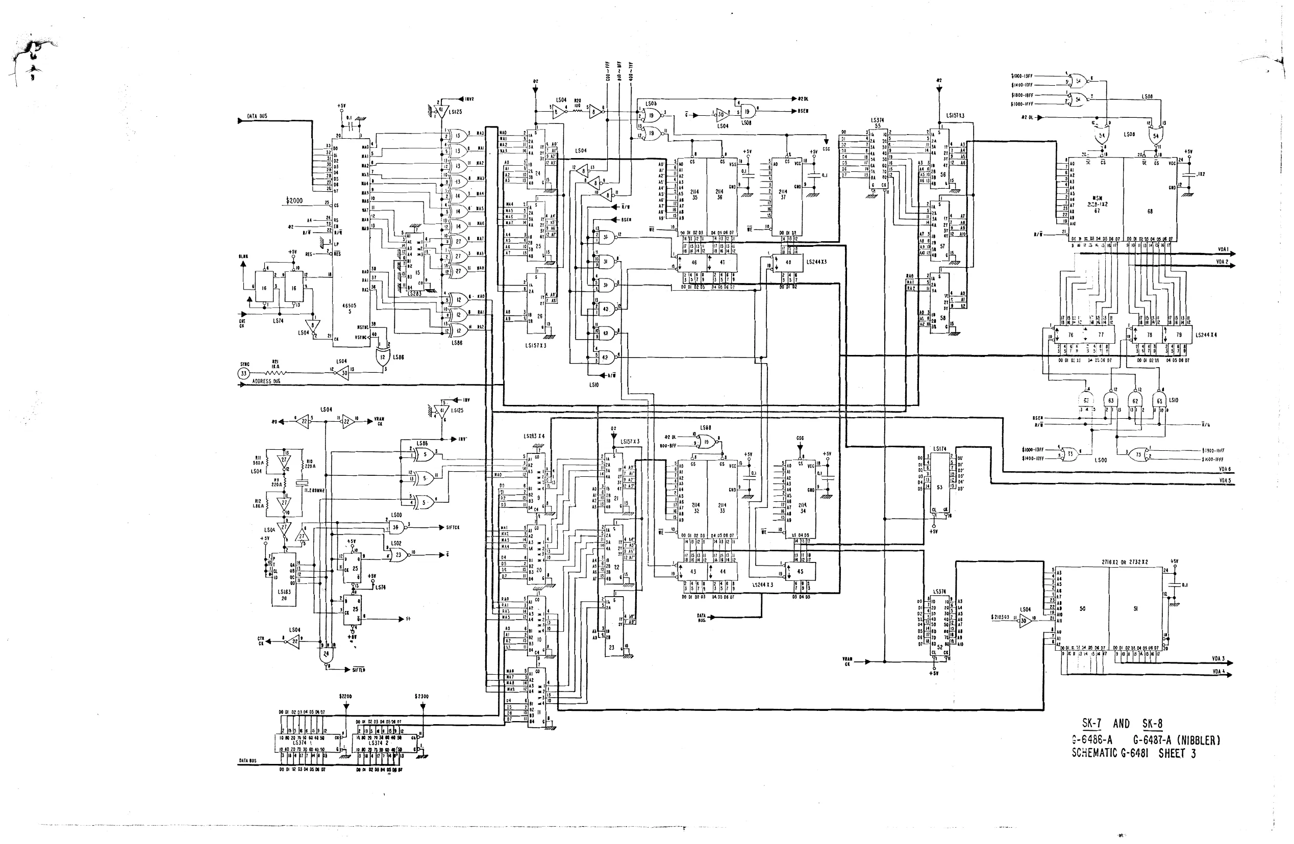
GAME P,.C, BOARD ASSEMBLY G-6480-A
ITEM PART NO. NO, DESCRIPTION REQ'*D
| 1 | G-6486-A © | SK-7 P.C, Board Assembly | 1 |
| 2 | G-6487-A | SK-8 P.C, Board Assembly | 1 |
| 3 | G-6145~A | 50 Conductor Ribbon Cable Assembly | 2 |
SK~7 P,C, BOARD ASSEMBLY G-6486-A
| ITEM | PART | °, | REF, | MFGR, |
| NO, | No, | DESCRIEION | DES, | PART NO, |
| 1 | G-6121 | Octal Buffer, Invert | Icl, Ic2, Ic3, | 74LS244 |
Ic4
| 2 | G-0686 | Exclusive Or | Ics | 74LS86 |
| 3 | G-6124 | 4 To 16 Decoder/ | Ic6é | 74LS154 |
Demultiplexer
| 4 | G-0960-48 | Game Program No, 1 | Ic7 | 2732 | |
| 5 | G-0960-49 Game Program No, 2 | Ics | 2732 | |
| 6 | G+0960~50 Game Program No, 3 | Ico | 2732 | |
| 7 | G-0960-51 | Game Program No, 4 | Iclo | 2732 | |
| 8 | G-0960-52 Game Program No, 5 | Ic12 | 2732 | |
| 9 | G-0960-53 | Game Program No, 6 | Icl4 | 2732 | |
| 10 | G-0960-54 | Game Program No, 7 | Ici5 | 2732 | |
| il | G-0960-55 | Game Program No, 8 | Icl6 | 2732 | |
| 12 | G-0960-56 | Game Program No. 9 | Icl7 | 2732 | |
| 13 | G-6129 | CPU | Icll | 6502 |
| 14 | G-6128 | 1024 X 8-Bit Static Ram | Icl3 . | 4118 |
| 15 | G-6127 | Monostable Multivibrator | Icl8 | 74121 | |
| 16 | 51991 | Timer | rcl9 | 555 |
| 17 | G-6126 | Hex Inverter | Ic20 | 74LS05 |
| 18 | G-6117 | Quad Bus Buffer Gate | Ic21 | 74LS125 |
| 19 | G-0679 | Hex Inverter | Ic22, 1¢27, 1039, | 74LS04 |
rc40
| 20 | G-0678 | Nor Gate | Ic23 | 74LS02 |
| 21 | G-0681 | Nand Gate | Ic24 | 74LS10 |
| 22 | 53706 | Dual D Latch | Ic25 | 74LS74 |
| 23 | “G-0690 | Binary Counter | Ic26 | 74L3163 |
| 24 | G-6120 | Octal Bus Drivér Invert | Ic28, ICc29, Ic30 | 74LS240 |
| 25 | G-6012 | Octal D Type Flip-Flop | Ic31, IC32, 1c33, | 74LS273 |
Ic34
| 26 | G-6125 | Dual 2-4 Line Decoder | Ic35 | 74L8155 |
| 27 | G-0677 | Quad 2-Input Nand Gate | Ic36, ICc42 | 74L800 |
| 28 | G-6020 | Quad Analog Switch | Ic37, IC47, IC55 | 4066 |
| 29 | G-0697 | Dual 4 Bit Counter | IcAl, 1c48, 1c49, | 74LS393 |
Ic54
| 30 | 52560 | Dual Timer | IC43 | 556 |
| 31 | G-0683 | Or Gate | Ic44 | 74LS32 |
| 32 | G-6181 | Sound Generator | Ic45 | SN76477 |
| 33 | G-6142 | Lower Power Quad Oper, | Ic46 | LM324 |
Amplifier
| 34 | G-0959-44 | Sound Program No, 1 | “| r052 | 2716 | |
| 35 | G-0959-45 | Sound Program No, 3 | ICc53 | 2716 | |
| 36 | G-6008 | 4 Bit Binary Counter | Ic38, IC56, IC57, | 74LS161 |
Ic58, IC59, IC6O, Ic61
| 37 | 52358 | Resistor 1/4 Watt 5% | RL, R2, R3, R4, | 2.2K OHM |
R5, R6, R14 :
| 38 | 51291 | Resistor 1/4 Watt 5% | R7, R46, R57, | 22K OHM |
R58, R59
| 39 | 50966 | Resistor 1/4 Watt 5% | R8, R52 | 100K OHM |
SK-7 P.C, BOARD ASSEMBLY _ G-6486-A ITEM PART REF, MFGR, no, | NO, DESCRIPTION _| DES, | PART NO.
| 34 | G-0959-44 | Sound Program No, 1 | Ic52 | 2716 | |
| 35 G~0959-45 | Sound Program No, 3 | Ic53 | 2716 | |
| 36 G-6008 | 4 Bit Binary Counter | Ic38, IC56, IC57, | 74LS161L |
Ic58, Ic59, IC60, Ic6l
| 37 | 52358 | Resistor 1/4 Watt 5% | RL, R2, R3, RA, | 2.2K OHM |
R5, R6, R14
| 38 | 51291 | Resistor 1/4 Watt 5% | Ri, R46, R57, | 22K OHM |
R58, R59
| 39 | 50966 | Resistor 1/4 Watt 5% | R8, R52 | 100K OEM |
| 40 53982 | Resistor 1/4 Watt 5% | RI, RLO | 220 OHM |
| 41 52563 | Resistor 1/4 Watt 5% | RLL | 560 OHM |
| 42 | 53863 | Resistor 1/4 Watt 5% | RU2 | > 1.8K OHM |
| 43 51294 | Resistor 1/4 Watt 5% | R13, R56 | 47K OHM |
| 44 |51564 | Resistor 1/4 Watt 5% | R15, R23, R30, | 1K OHM |
R31, R32, R35
| 45 | 51568 | Resistor 1/4 Watt 5% | RIG, RL7, R18, | 5.1K OHM |
R19, R20, R21
| 46 49264 | Resistor 1/4 Watt 5% | R22, R29, RA3, | 470 OHM |
RAG, RAS, RAG
| 47 50968 | Resistor 1/4 Watt 5% | R24 | 150K OHM |
| 48 51293 | Resistor 1/4 Watt 5% | R28, RA, | 10K OHM |
R61 Thru R70, R84
| 49 51292 | Resistor 1/4 Watt 5% | R33, R55 | 4.7K OHM |
| 50 52380 | Resistor 1/4 Watt 5% | R36 | 18K OHM |
| 5. | 51571 | Resistor 1/4 Watt 5% | R37 | 6.8K OHM |
| 52 53838 | Resistor 1/4 Watt. 5% | R39, R40 | 150 OHM |
| 53 52348 | Resistor 1/4 Watt 5% | R4l, R83 | 15K OEM |
| 54 49268 | Resistor 1/4 Watt 5% | RA7, R53 | 33K OHM |
| 55 53593 | Resistor 1/4 Watt 5% | R48, R50, R54 | 470K OHM |
| 56 | 53883 | Resistor 1/4 Watt 5% | R51 | 1,5 MEG OHM |
| 57 52734 | Resistor 1/4 Watt 5% | R60 | 1 MEG OHM |
| 58 53978 | Resistor Pack | RAL, RA2 | 1K OHM X 8 |
| 59 53892 | Capacitor, Electrolytic 25v | Cl, C2, C3 | 1000 MFD | |
| 60 | G-6173 | Capacitor, Electrolytic 1é6v | C53 | 47 MFD | |
| 61 | G-6169 | Capacitor, Electrolytic 16V | C57 | 100 MFD | |
| 62 | G-6174 | Capacitor, Film 25V | C52 | 21 MED |
| 63 G-6178 | Capacitor, Film 50V | c25 | 0033 MFD |
| 64 | G-0940 | Capacitor, Disc 50V | C4, €32, C33, | .001 MFD |
©34, c35, CSL
| 65 | 53994 | Capacitor, Disc 50V | C6, C41, C42, | 201 MFD |
c45
| 66 |G+6176 | Capacitor, Disc 50V | c54, C55 | 470 PF |
| 67 G-6177 | Capacitor, Disc 50V | c40 | 220 PF |
| 68 53993 | Capacitor, Disc 50V | c46 | 2200 PF |
| 69 G-6137 | Capacitor, Disc 25V | c8 Thru C23, | el MFD |
C31, C37, C39, c48, C50, C56 All PC
| 70 | G-0805 | Capacitor, Tantalum 35V | C5 | 047 MED |
| 71 52561 | Capacitor, Tantalum 16V | c7 | 10 MFD |
| 72 G-6179 | Capacitor, Tantalum 16V | c29, C30 | 22 MFD |
| 73 52359 | Capacitor, Tantalum 35V | C24, C38 | 1 MFD |
| 14 G-0811 | Signal Diode | D1, D2, D3 | IN914. |
| 75 | G-6166 | Crystal, 1),289 MHZ | X-TAL | |
| 76 G-6167 | Trim Control | VRL | 1K OHM |
77° | G-6168 Heat Sink
| 78 | G-6021 | Audio Amplifier | MB3712 |
19 52722 24 Contact Solder Dip skt 80 -]| 53711 40 Contact Solder Dip Skt 81 | G-6171 20 Circ, Right Angle Header w/Extractor 82 G-6172 50 Circ, Right Angle Header | CN1, CN2 w/Extractor 83 | ST-10945 | P.Cc, Board Support (5/8")
| 84 G-0940 | Capacitor, Disc 50V | PIN U To @ | 1000 PF |
ay +5 om t ous we
- Ht 24 2 Ls2dox 4 $2104 LS273x4 $2100
}2— MUSIC lio. LS—MUSIC Ig [&—MUSIC Ig, PARTM !2_paRT2m is ie Js0CL._ ac BOMB T $2101
Ont x 8
DIP Sw 8°’ crete Cas oo
ConTRoi Y po 2 Se =< optional < ner DiPswaP.do-7 if to —— 2 MUSIC 319 +S— MUSIC 39 TE—MUSIC 35
E
f2-BC 2 f&-Bc 3 2—MUSIC $210303 2 MUSIC 29 le MUSIC 210 po WARE Gf | 'S_music 26 HL Lsi66xa | 2 PLAY say 8 2 INV
| ‘a7! | 1 PLAY | & | I |
SIFTCK RI + ES Serco Ao-P—34 Yo} ——S2I04 Ai—p—)8 ivf 4—sa2ios Ae eHic ye} —s2i06. VDAG ct a
| + | = | dec _\vs}—s2i07 |
| Woe | 4 | IC352%012 —s2i00 |
i Lsisixz
shisha} cased Ls374x2 SK-T AN SK-8 Parr! G-6486-A — G-6487-A (NIBBLER) SCHEMATIC G-6481 SHEET | OF 3
+59 + Fi ‘o 8B i
- coal " . 5562 43 Th n ie " Ts
| L | o_o | eas | : |
ad orb 5 Tin E MT
PART 4
PART IM
PART 3 PART 2
| utsoe | | | PART 3N | T4Lso4 | 1 | PART 2N | HLSO4 | L |
| curt | w | cual | i | cunt | | |||
| 93 41 | cue 383 49 | cue Nas 54 | |||||
| ae | it | oe | n | 0 | |||
| oc AeA DC BOA | 2 | pop eadec BA | ORIG AP. | vty ku con MusiC 28 | |||
| Taya Be Ss fs Music | 7 7 TRE EY music | Tow BEE EP | MUSIC 29 | ||||
| WSIC39 | NUSICTS | [music Zio” | |||||
| rte 4? | MUSIC 310 | MUSIC 10 | |||||
| Hel st sts] el of of 23} 22} af | +50 | alata sl el af ol asl zehish | +59 | fel 34 | lt} a] 23] 22} ig | +50 | |
| AT AG ASAE AS AZ ALND A AD AID | valt | AT AS AS AR AS AZ AT AQABA AID | vr lZlt | AS AS AE i KO AT ADA ASAIO | vet | ||
| sf | ad | ee | sd | ||||
| 2116 51 | of | a6 §2 | cin | ang 83 | eee | ||
| Do bl be 03 | oy woe or | 100 bt 02 03, | oa oss or | {00 pt p03 | D4 05 08 tt | 8 | |
| 00) ay | a] 15) 1) | sy ay | aL 15] 6 a7 | Fol ay a | is) i) a | ||
| +5 | +5 | +51 | +5 | +5 | + | * | . |
| a) | +59 i | i | +5 | ||||
| ala} slg | Lalas} 6 | Lal al sf | al fg | al asl ¢ | als} of | ||
| iar ec | rare ec 0 dis | if ec 0au | Ika 8 fe hs | fas eo a | T4Ls02 | ||
| Cool sl | Isl | ost | | a it wal 'S | W | 0 |
56 ak o
| wis04 | “OUNE | 004 | ||
| Apes | T | T | ||
| t e | + | ¥ | ||
| 034: | 035 | +0 | i | |
| 1 | oT | sory | + | H |
| ee | ~ | A | [ | |
| fig CURT CURR | F | ‘of, ok | ! | |
| 393 48 | 2 | Ter vee gl | | | |
| fa 1008 ah | 20020208 ate | oe |
vs yg Hy ee a | nF
| a3 | 53 | ca | amputs | : | ||
| am | 4M | ber | nag dnez p63 dnt | Ase | we | |
| i | i | OK FioK Fi0K fi0K | 10K | RTE | ||
| Rs | t | i | ||||
| 6 | g | 3 | Gaur | as | ‘TOINPUTS, | ty R24 |
| ME | 4 | 31 | a | |||
| xastie | tt | ot | toe | |||
| 7 | ‘ | cot | i | :: | ||
| NE | a0 | Roos | ||||
| a | a | 10K | Bo. 8 | |||
| Fj | Tone | = | Moo | |||
| . | +5 | Wo | ||||
| @ | Ho | 8 |
woe @ is__fes wo. 8 ro wpurs Ny er
| x | ries | TeATT 45 | be |
IME 15k
SK-7 AND SK-8 G-6456-A G-6487-A (NIBBLER) j
| T | L | SCHEMATIC G-6481 SHEET 2 OF 3 | Hl |
ONE mag a0 ;
| BONA | Ri | cu | ||
| it | 03 | ANF | a | rn) |
> 22K 22k 2k cos Jt
This page is a drawing, shown as the original scan.