Centipede DP-182-3rd-01A
Centipede (revision 4) (Atari, 1980) · Drawing Package · 1 pages · original scan
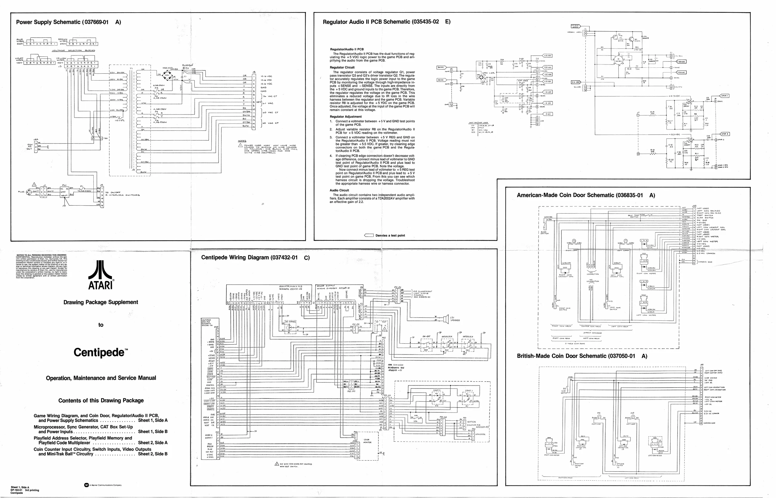
Power Supply Schematic (037669-01
‘a_o eeetct tow [betes es eT) wey fo A)
Ju weer sey) wae Regulator Audio Il PCB Schematic (035435-02 )
Regulator/Audio ! PCB The Regulator/Aualo II PCB has the dual functions of reg: uiting the +8 VOC fale power toe game PCB and am-
pilfying the aud from the game PC ‘pass transistor Q3 and Q3's driver transistor Q2. The regula
Regulator Circuit The regulator consists of voltage regulator Qt, power ‘pass transistor Q3 and Q3's driver transistor Q2. The regula- {or accurate regulates te lose power input othe game 8 by monitoring the voltage through high-impedance inpals FSENSE and — SENSE. The puts ae dec trom
barnes resistor RB is adjusted for the +5 VDC on the game PCB.
‘Once adjusted, the voltage atthe input of the game PCB wil
remain constant at this voltage Realtor Anton
1. Connect a voltmeter between +5 V and GND test points
of the game PCB.
- Adjust variable resistor RB on the Regulator/Audio 1! PCB for +5 VDC reading on the voltmeter.
- Connect a voltmeter between +5 V REG and GND on the RegulatoriAudio I PCB. Votage reading must not be greater than +55 VOC. i reat, claning edge jectors on both the game PCB and the Regular fonaudio Il PCB. If cleaning PCB edge connectors doesn't decrease volt. age difference, connect minus lead of voltmeter to GND. test point of RegulatoriAudio II PCB and plus lead to GND test point of game PCB. Note the voltage Now connect minus lead of veltmaterto +5 REG test point on Regulator/Augio Il PCB and plus lead to +5 V test point on game PCB. From this you can see which hhamess circult is dropping the voltage. Troubleshoot the appropriate harness wire or harness connector. ‘Audio Circuit ‘The audio circult contains two independent audio ampli fiers, Each amplifier consists of a TDAZOUZAV amplifier with an eifective gain of 22.
<1 Denotes a test point
Drawing Package Supplement
Centipede”
Operation, Maintenance and Service Manual
Contents of this Drawing Package sani Centipede Wiring Diagram (037432-01 C)
h ba
EE
Game Wiring Diagram, and Coin Door, Regulator/Audio II PCB, ona and Power Supply Schematics . . . Sheet 1, Side A ‘oe Microprocessor, Sync Generator, CAT Box Set-Up and PowerInputs.............0ceeeeee sees Sheet 1, Side B 7 Playfield Address Selector, Playfield Memory and so Playfield Code Multiplexer .................+ Sheet 2, Side A se Coin Counter Input Clreultns Switch Inputs, Video Outputs oe and Mini-Trak Ball™ Circuitry . eet 2, Side B “vom
Senate prin Gentpede mene TEPESTEESE (GETS SE TET OTe EE Ee Be ee
Anan ce