Soccer DP-144-1st-02B
Atari Soccer (Atari, 1980) · Drawing Package · 1 pages · original scan
SWITCH and TRAK BALL INPUTS
Sheet 2, Side B
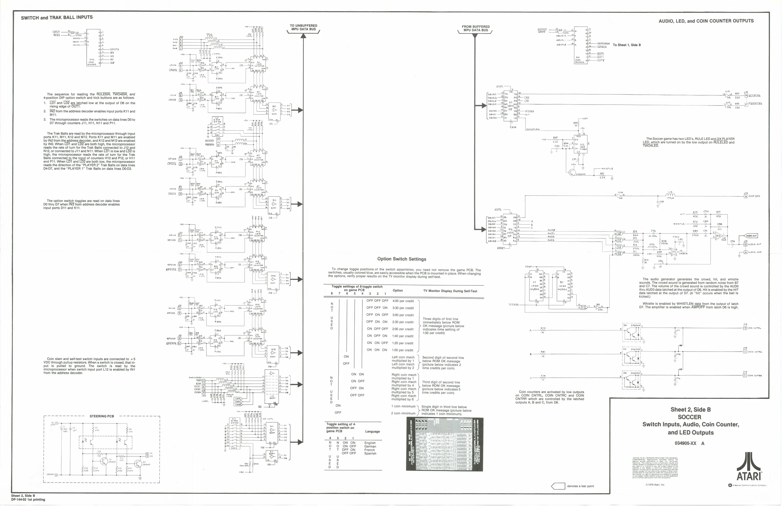
The sequence for reading the RULESW, TWOASW, and
‘4position DIP option switch and kick buttons are as follows:
1. TOT and TD2 are latched low at the output of D8 on the
rising edge of OUTT.
2. TNZ'rom the address decoder enables input ports K11 and
Mit.
- The microprocessor reads the switches on data lines DO to 7 through counters J11, H11, N11 and P11.
‘The Trak Balls are read by the microprocessor through input
ports K11, M11, K12 and M12. Ports K11 and M11 are enabled bby IN2 from the address decoder, and K12 and M12 are enabled by INO. When LD? and LD2 are both high, the microprocessor ‘reads the rate of tum for the Trak Balls connected to J12 and N12, or connected to J11 and N11. When LD1 is low and LD2 is high, the microprocessor reads the rate of turn for the Trak Balls connected to the input of counters H12 and P12, or H11 and P11. When LD1 and LD2 are both low, the microprocessor reads the direction of the “PLAYER 2” Trak Balls on data lines D407, and the “PLAYER 1” Trak Balls on data lines D003,
‘The option switch toggles are read on data lines Do thru D7 when IN3 from address decoder enables input ports D11 and K11.
Coin slam and selttest switch inputs are connected to +5 VDC through pullup resistors. When a switch is closed, that inut is pulled to ground. The switch is read by the ‘microprocessor when switch input port L12 is enabled by IN ‘rom the address decoder.
(oS ee ol
DP-144-02 1st printing wrieee (E
owe ‘TO UNBUFFERED MPU DATA BUS
woe FROM BUFFERED ‘MPU DATA BUS
Option Switch Settings
‘To change toggle positions of the switch assemblies, you need not remove the game PCB. The ‘witches, usually colored biue, are easily accessible when the PCB is mounted in place. When changing the options, verity proper results on the TV monitor display during selttest.
arene BL Toggle settings of Btoggle switch ‘on game PCB eres 4 Option TV Monitor Display During Selt-Test
ON ON
ON OFF
OFF ON
OFF OFF
oN
OFF
Toggle setting of 4 position switch on ‘game PCB
4324 NON ON 0 ON OFF T OFF ON OFF OFF ‘OFF OFF OFF
OFF OFF ON
OFF ON OFF
OFF ON ON
ON OFF OFF
ON OFF ON
‘ON ON OFF
ON ON ON
Language
English German French Spanish “400 per credit
3:90 per credit
3:00 per credit
2:30 per eredit
2.00 per credit
1140 per credit
120 per oredit
100 per credit
Left coin mech multiplied by 1 Lett coin mech multiplied by 2
Right coin mech ‘multiplied by 1 Right coin mech multiplied by 4 Right coin mech ‘multiplied by 5 Right coin mech multiplied by 6
1 coin minimum
2 coin minimum ‘Three digits of first line immediately below ROM (OK message (picture below Indicates time setting of 1100 per credit)
‘Second digit of second ine below ROM OK message (picture below indicates 2 time credits per coin)
Third digit of second tine below ROM OK message (picture below indicates 5 time credits per coin).
Single digit in third tine below ROM OK message (picture below icates 1 coin AUDIO, LED, and COIN COUNTER OUTPUTS
ic pe —varoraoe FSR To Sheet 1, Side B i
yrroree
cihesezeer game has wo LED's, RULE LED and 24 PLAYER D, which are tured on by the low output on RULELED and ‘TWOALED.
ra
re : Ele oo
‘The audio generator generates the crowd, hit, and whistle sounds. The crowd sound is generated from random noise from 87 {and C7. The volume of the crowd sound is controlled by the AUDO thru AUDS data latched at the output of D6. Hit is enabled by the HIT data latched at the output of D7. (A “hit” occurs when the ball is kicked) sn/nee isin
Whistle is enabled by WHISTLEN data from the output of latch
- The amplifier is enabled when AMPOFF from latch 06 is high.
falcon cures
fi} con cvrne,
Coin counters are activated by low outputs ‘on COIN CNTRL, COIN CNTRC and COIN CNTRR which are controlled by the latched ‘outputs A, B and C, from DB.
SOCCER Switch Inputs, Audio, Coin Counter, and LED Outputs
ATARI notes atest point