Pole Position CO-218-09 1st Printing
Pole Position (World) (Namco, 1982) · Change Order · 16 pages · 4 sections · original scan
~ ATARI > vere: conmuncanons Comoany
Parts List Changes
The metal attraction panel (part no. 039155-01) shown in Figures 1-2, 3-2, and 33, is not included in the Sit-Down Cabinet Assembly. This part may be ordered separately. Please contact your Atari representative for further information.
The following part number was changed in the Control Panel Assembly Parts List.
Part No.
A039229-01 A000608-09 72-JB3814S 7§-5512B
005255-04 039154.01 175002-004 pw 177010-244 Control Panel Assembly Parts List
Description
Upright and Sit-Down Cabinets
Steering-Wheel Control Assembly (Namco games use part no. A039229-02) Gear-Shifter Control Assembly #8-16 x .87-Inch Screw #%-20 x .75-Inch Black Carriage Bolt
Shifter Bezel Shifter Spacer #10 Flat Washer #%-20 Hex Locknut
The following part numbers were changed in the Steering-Wheel Control Assembly Parts List.
Part No. Steering-Wheel Control Assembly Parts List
Description
A035220-02 72-8008 72-8012 72-8408
72-HB3606S > 75-040S p> 75-044S 75-07014
79-58356 030369-01 035221-01 039230-01
039231-01 039232-01 039234-01 039243-01
035938-01 p> 04026401 107013-001 175002-001
175002-002 > 175009-170 178012-001 pw 178012-003
178027-001 178097-001 178099-003 178100-001
178101-001 178101-002 b> 178118-001 Coupler Printed-Circuit Board Assembly (inciudes Radial Optical Coupler) #10-32 x 0.50-Inch Steel Socket-Head Cap Screw #10-32 x 0.75-inch Steel Socket-Head Cap Screw #4-40 x 0.50-Inch Steel Socket-Head Cap Screw
#6-32 x 0.38-Inch Zinc-Plated Steel Hex Washer-Head Screw #10 Split-Lock Washer #4 Split-Lock Washer #4 Flat Washer
4-Position Connector with Locking Ramp (located on the Coupler PCB Assembly) Radial Optical Coupler (located on the Coupler PCB Assembly) 100 2, +5%, %W Resistor (located on the Coupler PCB Assembly) Steering Cap
Steering Shaft Spacer Steering Frame Steering Cap Label
Encoding Wheel Encoder Shaft Sin-One® Oil Fiat Washer
#10 Heavy Flat Washer Nylon Flat Washer Retaining Ring for 0.75-Inch Shaft Retaining Ring for 0.25-Inch Shaft
Nyogel 779® Lubricant Bearing for 0.25-Inch Shaft Steering Wheel Bearing Flange for 0.75-Inch Shaft
24 Diametral Pitch x 20° Pressure Angle x 2.500 Pitch Diameter Spur Gear 24 Diametral Pitch x 20° Pressure Angle x 0.583 Pitch Diameter Spur Gear ¥einch x Y-inch Sleeve Bearing
The following part number was changed in the Printed-Circuit Board Mounting Hardware Parts List.
Part No.
A037701-01 72-1404F 72-1604F p> 034536-03 Printed-Circuit Board Mounting Hardware Parts List
Description
U.S.-Built Upright and Sit-Down Cabinets
Electromagnetic Interference (EMI) Cage (includes guides) #4-40 x %-Inch Cross-Recessed Steel Screw #6-32 x %4-Inch Cross-Recessed Steel Screw Foam Pad
The following part numbers were changed in the CPU PCB Assembly Parts List.
Designator
c10 > cr c12 crs
C14, C15 C16-C23 C24, C25 C26 Central Processing Unit Printed-Circuit Board Assembly Parts List
Description
Capacitors 0.1 uF, + 10%, 25 V Ceramic-Dise Axial-Lead Capacitor 47 uF, 16 V Aluminum Electrolytic Fixed Axial-Lead Capacitor 0.1 pF, + 10%, 25 V Ceramic-Disc Axial-Lead Capacitor 0.01 uF, + 80%, -20%, 25 V Ceramic-Dise Axial-Lead Capacitor
0.1 pF, + 10%, 25 V Ceramic-Disc Axial-Lead Capacitor 0.01 uF, + 80%, -20%, 25 V Ceramic-Disc Axial-Lead Capacitor 0.1 uF, + 10%, 25 V Ceramic-Disc AxiatLead Capacitor 47 uF, 16 V Aluminum Electrolytic Fixed Axial-Lead Capacitor
0.01 uF, 100 V Radlal-Lead Mytar Capacitor 47 uF, 16 V Aluminum Electrolytic Fixed Axial-Lead Capacitor 0.0047 uF, 100 V Radial-Lead Mylar Capacitor 0.001 uF, 100 V Radial-Lead Mylar Capacitor
470 uF, 16 V Aluminum Electrolytic Fixed Axial-Lead Capacitor 22 uF, 35 V Aluminum Electrolytic Fixed Axial-Lead Capacitor 0.1 uF, + 10%, 25 V Ceramic-Dise Axiai-Lead Capacitor 0,001 uF, 100 V Radiai-Lead Mylar Capacitor Part No.
122002-104 24-160476 122002-104 122005-103
122002-104 122005-103 122002-104 24-160476
21-101103 24-160476 21-101472 21-101102
24-250477 24-350226 122002-104 21-101102
Integrated Circuits
| 2N | Type-12L6 Programmable-Array Logic 1 | 137316-001 |
| 3A | Type-28002 16-Bit Microprocessor | 137275001 |
| 3c | Type-74LS373 Integrated Circuit | 37-74LS373 |
| SF, 3H | Custom Integrated Circuit 10 | 137281-001 |
| 5A | Type-74LS74 Integrated Circuit | 37-74LS74 |
| 5c. | Type-12L6 Programmable-Array Logic 1 | 137316-001 |
| 8M | Type-74S04 Integrated Circuit | 37-74S04 |
Resistors
| R49 | 220 Q, | +5%, % W Resistor | 110000-221 |
| R50 | 1kQ, +5%, % W Resistor | 110000-102 | |
| R51 | 220 Q, +5%, % W Resistor | 110000-221 | |
| R52 | 470 2, +5%, v4 W Resistor | 110000-471 | |
| R89 | 100 kQ, +5%, % W Resistor | 110000-104 | |
| R9O-R92 | 1kQ, +5%, % W Resistor | 110000-102 | |
| R98 | 4.7 kQ, +5%, v4 W Resistor | 110000-472 | |
| Reg | 220 Q, + 5%, 1% W Resistor | 110000-221 |
The following part numbers were changed in the Video PCB Assembly Part list.
Video Printed-Circuit Board Assembly Parts List
| Designator | Description | Part No. |
Capacitors
| & C3-CI7 | 22 uF, 35 V Aluminum Electrolytic Axial-Lead Capacitor | 24-350226 |
Resistors
| R62 | 2.2 kQ, +5%, % W Resistor | 110000-222 |
| hm R63 | 1kQ, +5%, % W Resistor | 110000-102 |
| wm R64, RES | 822, +5%, % W Resistor | 110000-820 |
| R66 | 220 Q, +5%, % W Resistor | 110000-221 |
| R67 | 470 Q, +5%, %4 W Resistor | 110000-471 |
| R68 | 1kQ, +5%, % W Resistor | 110000-102 |
| R69 | 2.2 kQ, +5%, 4 W Resistor | 110000-222 |
| wm R70 | 1kQ, +5%, % W Resistor | 110000-102 |
| wp R71, R72 | 82 Q, +5%, vs W Resistor | 110000-820 |
| R73 | 220 Q, +5%, % W Resistor | 110000-221 |
| R74 | 470 Q, +5%, 4 W Resistor | 110000-471 |
| R75 | 1kQ, +5%, % W Resistor | 110000-102 |
| R76 | 2.2 kQ, +5%, 4 W Resistor | 110000-222 |
| R77 | 1kQ, +5%, % W Resistor | 110000-102 |
| > R78, A79 | 82 2, +5%, % W Resistor | 110600-820 |
Transistors
| Bm Q1-04 | Type-2N3904, 60 V, 1 W, NPN Transistor | 34-2N3904 |
| pm 05-07 | Type-2N3706, 40 V, 1 W, PNP Transistor | 33-2N3906 |
The following part numbers were changed in the Foot-Pedal Control Assembly Parts List.
Foot-Pedal Control Assembly Parts List
Part No.
> 19-9026 72-8606 040028-01 b> 177010-240 Description
Upright and Sit-Down Cabinets
5 kQ Potentiometer Acceptable substitute is part no. 19-9022 #6-32 x .38-Inch Hex Socket-Head Cap Screw Compression Spring (for pedal) #10-24 Hex Locknut
The following part number was changed in the Utility Panel Assembly Parts List.
Utility Panel Assembly Parts List
Part No. Description
176018-002 #6-32 x VY2-Inch Thread-Forming Screw 75-9910WO #'%.-32 Stamped Nut 178070-001 Volume Control Knob b> 179125-001 Grounding Clip
Illustration Changes
Please note the changes made to the Steering-Wheel Control Assembly illustration which are indicated by this symbol:
178099-003 ah 039243-01 = (Label) r (Steering whee!)
03923001 (Steering cap)
039231-01 (Shaft)
175003-002 (Nylon washer) 178012-002 (Retaining ring)
72-HB3606S. (Hex screw)
178100-001 f uae rm" (Flange bearing) 178097001 (Bearing assy.) 175002-001 178118-001 (Washen) Qn (Sleeve bearing)————_} S 175009-170 0 (Nylon, washes) 178012003 . (Retaining ring) On (Encoder shat) Mu 101.002 178101-001 wioean = 175002-002 Heavy washer) wa 75-040 = vG (Washer) f (Encoding wheel) 72-8008 pres (Screw) STONE (Washer) eee = NYOGEL 779 75-044 (Splitock washer) —— Gore i$ = SHN-ONE OIL
Figure 3-5 Steering-Wheel Control Assembly U.S.-Built A039229-01 E lreland-Built A039229-02 E
Figure 3-4: Part no. 75-945S (Hex locknut) changed to 177010-244.
Figure 3-9: Part no. 75-941S (Hex locknut) changed to 177010-240.
Figure 3-15: Part no. 75-916S (Hex nut) has been replaced by part no. 179125-001 (Grounding clip).
Figure 3-18: Part no. 034536-02 (Foam pad) changed to 034536-03.
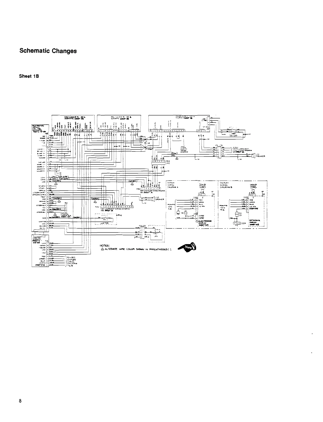
This page is a drawing, shown as the original scan.
Sheet 48
C85-C88 have been added.
Sheet 5A
Microprocessor A
nase.
contd Integrated Circuit 5C part no. changed to 13716-001.
Sheet 5B
Integrated Circuit 2N part no. changed to 13716-001.
integrated Circuit 8M changed from LS04 to S04.
Sheet 6A
R98 changed from 2.2 kQ to 4.7 kQ.
ii i
as]
Signal names SBABO-SBAB9 changed to SABO-SAB9. ii ele [a fo[e faye ais /ays.
ielaeser
s/s
Soe oe
Sheet 7A
CPU PCB Sync Chain
Value of R50 changed to 1 kQ.
sasser +
- USED INSHEET 5a +58
Sheet 8A
Brake and Gas Pedal Input
a ‘System Bus Interface
a:
Sheet 8B
Option Switch Input and 1/0 Interface
Integrated Circuit 8M changed from LS04 to S04.
Sheet 15B
Color Memory and Output
Transistors Q1-Q3 have been added. Resistors R63, R70 & R77 have been added. Resistors R103-R105 are not loaded.
This page carries no recoverable text. It is a drawing or a photograph. See the original scan.
This page carries no recoverable text. It is a drawing or a photograph. See the original scan.