Cosmic Guerilla
Cosmic Guerilla (Universal, 1979) · Manual · 25 pages · 21 sections · original scan
COSMIC
GUERIA
Operation, Maintenance and Service Manual
UNIVERSAL
CONTENTS
|. Features of this machine -1
- How to handle and maintain this machine. 2 IIL How to play 3 IV. Nomenclature of each part... 2... eee ee eee eee 4 A. Nomenclature of cabinet parts B. Drawing of circuit board mounting position C. Positions of dip switches and volume controller knobs
- Setting the option (dip switches). .......... 00 c eee eter eee 6
- Volume controller knob . .
- Fuses in the power unit. Ve. TV monitor... 6.6.66. e eee eee A. Adjustment of TV picture screen VI. Parts catalog A-1 Component parts related to cabinet (outside) . A-2 Component parts related to cabinet (inside)
- Operating panel assembly
- Door assembly and parts list...
- Lever assembly and parts list B. Component parts related to switches in the cabinet C. Circuit board IC location and parts list
- Main circuit board IC location. .
- Main circuit board parts list.
- Sound circuit board IC location,resistance setting and resistance location
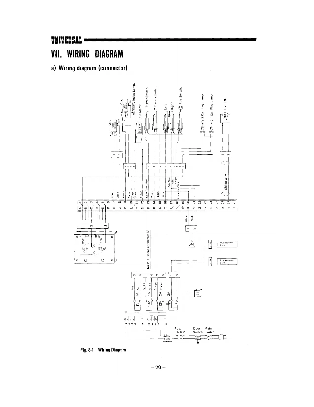
- Sound circuit board parts list . VII. Wiring diagram
- Wiring diagram (connector)
- Schematic diagram (23"’). .
- Schematic diagram (20''). Postface.
Fig. 1-1 Fig. 2-1 Fig. 2-2 Fig, 3-1 Fig, 3-2 Fig. 3-3 Fig. 4-1 Fig. 5-1 Fig. 5-2 Fig. 5-3 Fig. 5-4 Fig. 5-5 Fig. 6-1 Fig. 7-1 Fig. 7-2 Fig. 8-1 Fig. 8-2 Fig. 8-3 REFERENCE DRAWING
Nomenclature of Cabinet Parts... 0.0... 00 cee ee eeee teen eeeeee 4 Circuit Board Mounting Positions... 6.0.0... 6c cece e eee ence eee 5 Side View of Circuit Board Mounting Positions................0eee0e 5 Positions of Dip Switches. 6... 0.0... cece cece eee eee ene 6 Position of Volume Controller Knob «1.2.0.0... ee eee eee eee 7 Fuses in the Power Unit... ccc cee eens The Inside Drawing of Front Door Component Parts Related to Cabinet (Outside) Component Parts Related to Cabinet (Inside)..............-.---00- Operating Panel Assembly... 0.0... 0. cece cece eee eee e eee eee Inside View of Door Assembly ........ 0. eee cee eee eee eee Lever Assembly... 0... 0... cece eee eee . Component Parts Related to Switches in the Cabinet................. 14 Main Circuit Board 2.0... eee eee eee cere eee eens 15 Sound Circuit Board 2.6.6... cee cece eee ee eee eee 18 Wiring Diagram... 0. eee cect e ee ete eens 20 Schematic Diagram (23") . . . ~. 21 Schematic Diagram (20) 0... 0. eee cece tenes 22
21h canons osune-at ecm art btn ednesaitestinanieainan stan adit en atabat oan uDsaDaIee amas t tA Se ete ee
Jeans attiemcntsansescies amici stti-cinyeatib-atn api anest at
- WHEN ORDERING PARTS —
Since each component part is indicated by block, definitely specify both the corresponding Fig. No. and part No. within : : i i i i the Fig. when placing an order for it. 2
epee HL Eee er TH tee as
. FEATURES OF THIS MACHINE
- The game packs in excellent features capturing the hearts of players.
- The lever control system is simple to handle.
- At the flick of a dip switch, you can select among extended play, the number of laser guns and time of appearance of an additional laser gun, etc.
- High score for the day is always displayed on the screen.
- Finely designed cabinet and fascinating acoustic effects.
1,
HOW TO HANDLE AND MAINTAIN THIS MACHINE
Since the UNIVERSAL’s COSMIC GUERILLA employs a color TV receiving set, be careful not to shake it during transit and when carrying it about.
Install it at a location which is not exposed to direct sunlight. In order to prevent the inside temperature rising, avoid as much as possible a location near a heater, etc.
Since the grounding terminal is visible, be sure to connect it to a grounding conductor.
Insert the power cord into the outlet and turn on the switch.
Even if the solid-state module seems to be out of order, do not check the circuit by means of a circuit tester, etc., since the internal voltage of the tester, etc. may sometimes break down the IC.
Make sure the machine is well ventilated. |f the temperature of the IC and transistor is lower than 60°C, they function normally and may be considered reliable. If it exceeds 60°C, their performance cannot be guaranteed.
Make sure that the connector, etc. is not disconnected.
Whenever connecting the power cord of the solid-state module to, or disconnecting it from, the outlet, be sure to turn the power off.
Although the products of UNIVERSAL are manufactured with the utmost care, they may develop malfunctions when used for long periods. So, be sure to check this machine daily.
1.
HOW TO PLAY
Drop ina coin when playing by yourself. Drop in two coins when playing with a friend.
When pressing either one- or two-player button after inserting a coin or two, the game starts. Play it by handling a lever for moving the laser guns from side to side and a FIRE button.
UFO UFO appears flying behind the guerillas as they race towards the front of the screen. Here’s your chance to shoot the UFO down and add up points. But if you get too absorbed in it, you expose your laser guns to danger. When you hit the UFO, your score — either of 50, 100, 150 or 200 up to 300 points — is displayed at random.
Guerillas The guerilla rushes towards your block from both sides to take it away while bombing. When the block disappears, he tries to take away the central laser gun to his position. They are your targets. Wipe one off and your score piles up. Depending on the type of guerilla you get 20, 40, 50, 60 and 100. When you destroy all the guerillas on the screen, a new bunch of guerillas appears closer to your laser guns, making the game more and more difficult.
Station There are two stations for protecting your laser guns from the guerillas’ direct assault. The point is to wipe off as many guerillas as possible. Your stations will be gradually destroyed by missiles launched by the guerillas. Be careful! As each new group of guerillas reappears, your destroyed stations come back on the screen.
Laser guns You can dodge the guerillas by moving your laser guns sideways with the lever controller knob. Press the FIRE button to launch the laser missiles. Hit a guerilla and it vanishes with a horrifying shriek, The key to mastering the game is skillful operation of the laser gun and well-timed missile launchings. When each laser gun is destroyed, a reserve gun at the left bottom of the screen appears and the game continues. (Play by turns when playing with a friend).
Reserve guns The remaining number of laser guns is displayed at all times. The game continues until all the laser guns are destroyed. If your score reaches a certain level, you are awarded another stock of laser gun as a bonus.
- The number of laser guns and the setting of bonus points, etc. can be selected with dip switches.
Block It protects the central laser gun. If the guerilla is shot before he takes away the block, it returns to its location.
Mutant mole It appears every time you score 500 points, attacking your laser guns.
~3-
IV. NOMENCLATURE OF EACH PART
A. NOMENCLATURE OF CABINET PARTS
Title panel fixture Title panel
CRT
Cabinet proper Resin cover
J player, Button
Sticker for game rules
Operating panel face
Door (front)
Coin slot |_—- Cash box door
Caster
Fig. 1-1 Nomenclature of Cabinet Parts
4a
B. DRAWING OF CIRCUIT BOARD MOUTING POSITION
TV circuit board
Main circuit board
Sound circuit board
Power source unit \
Fig. 2-1 Circuit Board Mounting Positions
Main circuit board and its container
Fig. 2-2 Side View of Circuit Board Mounting Positions
C. POSITIONS OF DIP SWITCHES AND VOLUME CONTROLLER KNOBS
‘J MAIN CIRCUIT BOARD
Dip switches | °"| gHeaee
SSSSS wwwww 12345 Osa Fig. 3-1 Positions of Dip Switches
- Setting the option (dip switches)
COSMIC GUERILLA is designed to have various operations and options set by the ON-OFF combinations of the dip switches. When starting a game, choose any desired game option and set the dip switches accordingly.
- Setting the number of laser guns according to score: (Dip switches SW1, 2)
| Score | swt | sw2 |
| 2000 | OFF | OFF |
| 1500 | ON | OFF |
| 1000 | OFF | ON |
0 ON ON
(Set at 2,000 points when shipped)
- Setting the game charge:
Credit sw3 1 coin 1 play ON 1 coin 2 plays OFF a
- Setting the number of laser guns:
Number of laser guns sw4 3 ON 5 OFF
(Set at 3 laser guns when shipped)
- Change-over setting of the mode of game (SW5): The game may be enjoyed either as an upright or table type. (When used as a table type for 2-player action, the table turns over.)
For upright use... ..... ON For table use ......... OFF
(Be sure to place SW6 in the OFF position at all times, since it is not related to the game.)
- Volume controller knob
(Fuse) - Sound circuit board
Main circuit board ~~ Volume controller knob (The volume increases when turned in the arrow-marked direction)
Fig. 3-2 Position of Volume Controller Knob
- Fuses in the power unit
TV use table tap 120V
3A 120V, for TV 3A 6.3V, for lamps
3A 100V, for the main use
Fig. 3-3 Fuses in the Power Unit
VI. PARTS CATALOG
A-1 COMPONENT PARTS RELATED
TO CABINET (OUTSIDE)
Fig, 6-1 Component Parts Related to Cabinet (Outside)
OUTSIDE CABINET PARTS LIST
Ref. No. | Name _| 1 Title panel
| 2 | |. | Mlustrated glass A |
3 Illustrated glass B 4 “CRT 5 Cash box door 6 Sticker for game rules
[ 7 Push button (Fire)
8 Cabinet proper | 9 Knob 32-Dim.
10 Coin indication panel
| 11 | L | Title panel fixture |
| 12 | | | Caster |
13 Coin slot 14 Main door 15 Push button (1 player) 16 Push button (2 players) 7 1 or 2 players indication panel 18 Lever indication panel
| 9 | | | Control lever ( general name) | | |
-~9— URITERSAL
A-2 COMPONENT PARTS RELATED TO CABINET (INSIDE)
a — Operating panel assembly b— Door assembly
Fig. 5-2. Component Parts Related to Cabinet (Inside)
- Operating panel assembly
Switch ass’y for 2 players Lever assy
Miniature lamp Switch ass’y for 1 player Fire button switch assy
Fig. 5-3 Operating Panel Assembly
- Door assembly
Fig. 5-4 Inside View of Rejector Assembly
-mM1-
REJECTOR ASSEMBLY PARTS LIST
Ref. No. Name 4
1 Main door [2 Returning soucer 3 Lamp & plastic plate bracket 4 Bearing 5 Coin slot shute
| 6 | Returning button | 7 |
7 Coin slot 8 Slot plate 9 Transmission shaft
10 Rotary bracket
uv | Rejector bracket
| L | 12 | Rejector case | _ |
13 Coin slot shute holder
| 14 | Rejector | i |
15 Sensor slot 16 Micro switch
17 Key sets 19 Miniature lamp socket
18 Miniature lamp
20 __ Coin indication panel
21 Hexagon socket head screw 22 { Slam switch 23 Slam switch holder
=—12=
URITERSAL
- Lever assembly and parts list
Fig. 5-5 Lever Assembly
LEVEL ASSEMBLY PARTS LIST
[ Ref. No. | Name 1 Knob 32-Dim. 2 Lever shaft
3 Lever guide & stopper 4 Transmission bar 5 Nut with stopper 6 Switch bracket
7 Spring 8 Spring holder 9 Blades switch
10 Blades switch 11 Spring holder with nut 12 Bolt 13 Bolt
=13-—
URIVERSAL
B. COMPONENT PARTS RELATED TO ice SWITCHES IN THE CABINET
Fig. 5-6 Component Parts Related to i y ra ‘Switches in the Cabinet ‘Too y
INSIDE CABINET PARTS LIST
Ref. No. Name | 1 Fluorscent lamp assembly 2 Fluorscent lamp assembly 3 Blades switch 4 Blades switch 5 Blades switch 6 _Blades switch 7 Miniature lamp assembly 8 Micro switch 9 Miniature lamp assembly 10 Miniature lamp assembly 11 Door switch 12 Toggle switch 13 Micro switch
14 Slam switch i]
at a 1
C. CIRCUIT BOARD IC LOCATION AND PARTS LIST
- Main circuit board IC location TYP YH ERO 9.828 MHz al [al (38|>) |= Ss RR & LJ ai lal js a) LIW WW ie Feil fy i 5 Sa)
z
Te a ay E
£ zl lel is} 18 8 a) 18) 18) 12 a z LJ LJ Ld
8 g [) ome] f essere B
0 556 A
Fig. 7-1 Main Circuit Board n
- Main circuit board parts list
[1] Integrated circuit
| Item No. | Q'ty | Description |
| SN7400N| | 1 | Transistor Logic |
| 02N | 1 | ia |
| 04N | 3 | Zi |
| o8N | 4 | EB |
| 30N | 1 | " |
| 74N | 2 | " |
| 86N | 3 | z |
| 125N | 1 | : |
| 153N | 4 | 7 |
| 154N | 1 | " |
| 155N | 1 | v |
| 157N | 1 | ie |
161N 1
| 166N | 2 | " |
251N 2 7
| 259N | 3 | 7 | |
| 298N | 1 | “ | |
| 365N | 2 | a | |
| NE 556N | 1 | Dual timer | _ |
| TMS4116 | 8 | _Neh mos 16k bits RAM | |
| TMM333 | 2 | Neh mos 32k bits ROM | |
| zeoso, | | | 1 | Nch mos CPU |
| unooo2 | | | 1 | NchmosCRTC |
| uA78HO5 | 1 | +5V voltage regurator | |
| HA7812 | 1 | __ +12 | i |
| HA7905 | 1 | -5V | a |
[2] Other semiconductor devices
| Item No. | Q'ty | Description | |
| ULN2003 | 2 | Darlington transistor array | |
| S5VB | 2 | 5 Ampere rectifire bridge | |
| S2VB | i | 2 Ampere | 7 |
| TLR301 | 3 | LED (RED) | |
| 1$1588 | 2 | Switching diode | |
| RD7AN | 1 | Zener diode (7.1—7.8V Avaranche) | |
3] Capacitors
Rating Q'ty | Description 10,000. F/16WV Chemical capacitor 6,800uF/35WV 1,000n F/25WV 22uF/35WV 10p F/16WV 4.7uF/25WV O.1nF/12WV 70 Ceramic capacitor 0.01HF/12WV : z
100pF/12WV
[4] Resistors
Q Z Rating MS1028
200 ko 1/4 W 100k2”
47kQ
3kQ ” 2kQa 1.6kQ
12kQ "
TkQ
5102”
3302”
1002”
10a” Description 1kQ Resistor array | Carbon solid resistor wlalsjolm/a}a)/sfaja]a}ain
5] Misc
Name Q'ty Description DIP SW X'tal
Fuse 8 element switch array
9.828 MHz 1A
3A 5A
~17—
URIVERSAL
- Sound circuit board IC location, resistance setting and resistance location
‘sl Gt
*CHD+ —)2003ANI
= 1000 wF/25V
@PC1181H
47u 25V 1000 uF /25V
HPC1181H : TWSY3AINN
S—-LO6L
Fig. 7-2 Sound Circuit Board
~—18—
- Sound circuit board parts list
[1] Integrated Circuit
| Item No. | O'ty | Description |
LM324 Quadruple Operational Amplifiers Dual Timer _ -
Darlington Transistor Array 4
18-stage Static Shift Register Quad 2-Input EXCLUSIVE-OR Gate ‘Quad 2-Tinput NAND Schemitt Trigger
| uPC1181 | 2 | Power Amplifiers |
ce ec s =) Ss @ wo] a} a) a] ro] 5
[2] Other Semiconductor Devices
| Item No. | O'ty | Description |
| 181588 | 4 | Switching Diode |
28C945 1 __N-P-N Transistor - J [3] Capacitors
| Rating | ory | Description | ] |
2.2 uF SsOWV Chemical Capacitor 10 uF 16WV “ 47 uF 25WV 220 uF 25WV 470uF _25WV 1000 pF 12V 0.01 uF 12V 0.1 uF 12V 0.1 uF 50V 0.0033 uF 50V 0.0068 uF_SOV 0.01uF 50V 0.068 uF 50V 0.47 uF 12WV Ceramic Capacitor
Polyester Film Capacitor Bln} a] a] ala} o) a) a} m}ro/ro] too
Tantalum Capacitor
[4] _ Resistors Rating
4.72 100 2 TkQ 2.2k2 47 kQ 10kQ 22kQ S1KQ 100 k2 [150 k2 [200 k2 220 kQ 510 kQ 680 kK® 1MQ Description Carbon Solid Resistor wI9 E
~|4[oly|ats)=]e]-)a)a}afala|_
[5] Mise
| Name | I | O'ty | I | Description |
24P Wire Wrap Socket | 1 [
-~19—
This page is a drawing, shown as the original scan.
soxremnar MANUAL @ nay (CRTC) 32
1 (24 in DIP) [MAIN BLOCK DIAG
(CRTC) v2
ADDRESS HIGH — ‘TO 2708 CHIP SELECT Low. ADDRESS es? ACTIVE HIGH at thie point alone
feared
CK DIAGRAM}
actoov
acioov
To Color Tv actov 2a (26 Aewat
acrv o nev Wor Audi)
a Be} ___—o n12v
ode. LI sev
COSNIE GVERULA,
7907A
UNIVERSAL
ce
nev
con EXTEND
+ gor MONSTER
GUN sor
GUN o1sTROY:
GOT BONUS
BONUS CHANCE
KILLER
Marc {.s8) (ws8) (cso)
mance ENABLE
music
SOUNDS (T) IR
+ MuTING. SOUND BLOCK DIAGRAM
tev 22480 108z TO No.9 Pin of 1181, 2003
151588 x 2 +8
no 6
2.20 a apeit ee bal ty 401 1200 Music MARCH ENABLE MARCH (LSB! iwser (Gse) KILLER GoT BONUS. BONUS CHANCE GUN DIsTROY
ano.
ox
682k
sox
a Connection} assignment b+ (Top View) /COIN EXTEND. ‘GOT MONSTER GUN SHOT
wonitey
(wuz)
(Gun sHoT
(GUN o1sTROY?
(eonus)
(KILLER ATTACK?
(ATTACK MARCH!
(music
(oniver
(muTING)
cos
7907B
UNIVERSAL