Thunder Blade Economy Upright Type (5798-01)
Thunder Blade (upright) (FD1094 317-0056) (Sega, 1987) · Manual · 34 pages · 24 sections · original scan
HOUND ER ELGLE
ECONOMY UPRIGHT TYPE
OWNER'S MANUAL
TABLE OF CONTENTS
INTRODUCTION TO THE OWNER’S MANUAL HANDLING PRECAUTIONS ...........eeeetceesseeteeeenenene . PREVENTION OF COUNTERFEITING AND CONVERSION .. . PRECAUTIONS CONCERNING THE PLACE OF INSTALLATION NAME OF PARTS 1 NAME OF PARTS .2 . SERVICE SWITCH FUNCTIONS RENE
. OPENING THE CONTROL UNIT AND ADJUSTMENT . DIP SWITCH SETTING .............. . EPROM/MASK ROM LOCATIONS .
- SELF - TEST ..
- PARTS LIST...
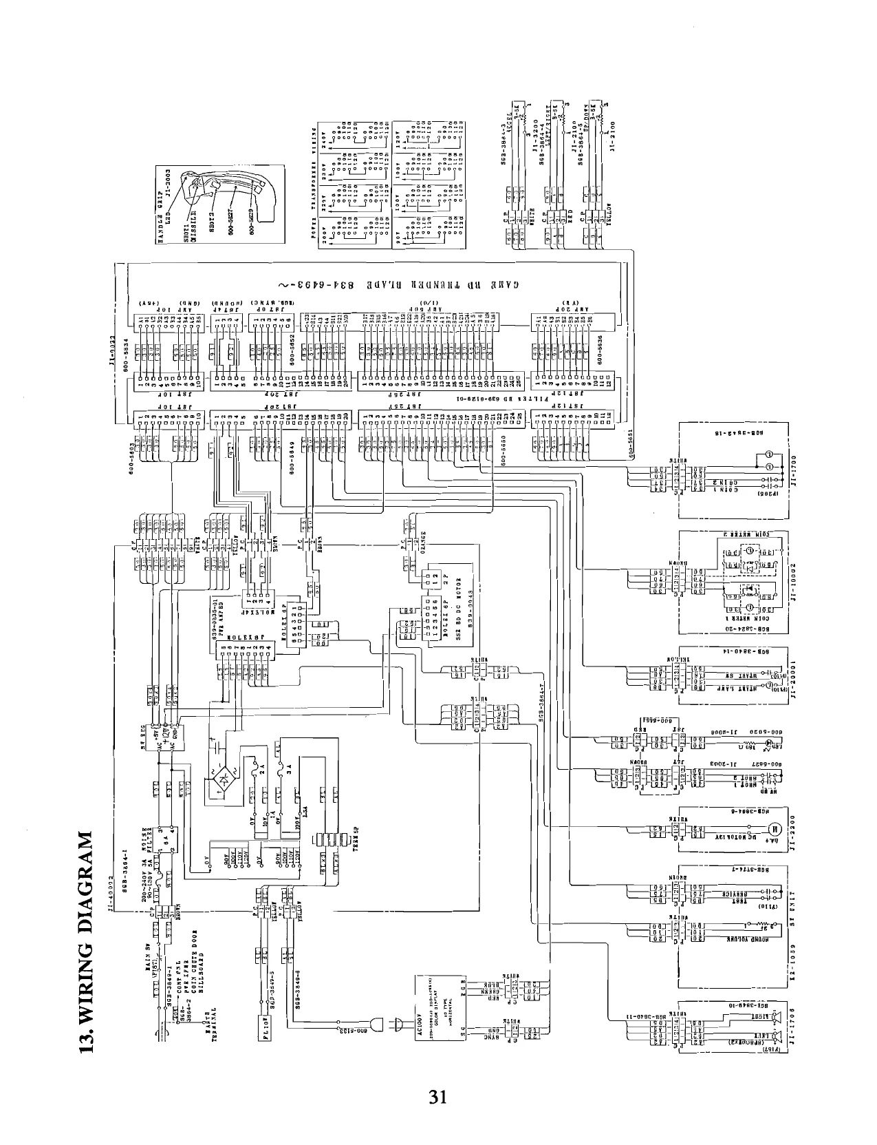
- WIRING DIAGRAM WWIAANA
SPECIFICATIONS
INSTALLATION SPACE ; 700 mm (27.6 in.) W X 550mm (21.6 in.) D HEIGHT : 1650_mm (65.0 in.) POWER : 145 W CRT. : 20" MONITOR WEIGHT : 95 kg (209.4 Ibs.)
INTRODUCTION TO THE OWNER’S MANUAL
SEGA ENTERPRISES, LTD., supported by its high electronic technology of LSIs, microprocessors, etc. and a wealth of experience, has for more than 30 years been supplying various innovative and popular game machines to the world market. This OWNER’S manual is intended to provide detailed comments together with all the necessary information covering the operation in general of electronic assemblies, electromechanicals, servicing control, spare parts, etc. as regards the THUNDER BLADE ECONOMY UPRIGHT, a new SEGA product. The manual is intended for those who have knowledge of electricity and technical expertise especially in ICs, CRTs, microprocessors, etc. Carefully read so as to acquire sufficient knowledge before working on the machine. Should there be a malfunction, non-technical personnel should under no circumstances touch the interior system.
- HANDLING PRECAUTIONS
When installing or inspecting, be very careful of the following points and pay attention to ensure that the player can enjoy the game safely. ¢ Be sure to turn the power off before working on the machine. ¢ To insert or pull out the plug quickly is dangerous. Itis necessary to make sure that the power cord or the grounding wire is not exposed on the road, etc. in a manner so as to be dangerous. Make sure that grounding connections are made safely at the position where so specified.
- Donot use any fuse that does not meet the specified rating. « Make complete connections for the IC board and other connectors. Insufficient insertion is very dangerous.
Also, for the IC board circuit inspections, only the logic tone is allowed. The use of a tester is not permitted, so be careful in this regard. After confirming that there are no irregularities, turn the power ON.
- PREVENTION OF COUNTERFEITING AND CONVERSION
LABELLING To prevent counterfeits and conversions, the following labels are put on all the SEGA products. When handling such goods, be sure to confirm the labels. They are used to prevent illegal acts such as the unauthorized copying of the products and the printed circuit boards thereof or carrying on business by manufacturing similar merchandise or by converting, selling or using such products or printed circuit boards.
ORIGINAL SEAL LICENSE SEAL The following seal is put on the The following seal is put on the kits , such as the printed circuit boards machines manufactured by SEGA products. SEGA FY oF) S RIGINALSEAU
sue ORIGINAL SEAL THUNDER BLADE NO Fon tartans mo
COPYRIGHT NOTICE This SEGA product has the copyright notice as follows: © SEGA 1987
This signifies that this work was disclosed in 1987 and is the property of SEGA ENTERPRISES, LTD.
- PRECAUTIONS CONCERNING THE PLACE OF INSTALLATION
The THUNDER BLADE ECONOMY UPRIGHT is an indoor game machine. Absolutely do not install it outside. Even indoors, avoid installing in places mentioned below so as to ensure proper usage: Places subject to rain or water leakage, or condensation due to humidity. In the proximity of an indoor swimming pool and/or shower. Places subject to direct sunlight. Places subject to heat sources from heating units, etc., or hot air. Vicinity of highly inflammable/volatile chemicals or hazardous matter. Sloped surfaces. Vicinity of anti-disaster facilities such as fire exits and fire extinguishers. Places subject to any type of violent impact. Dusty places. ey
4, NAME OF PARTS (1)
DESIGN PLATE
CONTROL UNIT
TOOLS |
(TAMPERPROOF WRENCH) (TAMPERPROOF DRIVER)
M4 540-0006-01 M4 540-0018 MS 540-0007-01 MS 540-0017 M6 540-0015-01 M8 540-0011
4. NAME OF PARTS @)
SWUNIT
ASSY POWER SPLY —_——_—_——= ‘SHIELD CASE
§. SERVICE SWITCH FUNCTION
The layout as shown below can be viewed by opening the coin chute door.
1 SERVICE SWITCH 2 TEST SWITCH
COIN CHUTE DOOR
CASHBOX 3 VOLUME ADJUSTMENT
Used for the purpose of servicing and increasing the credits without registering on the meter (this allows you to check the game).
@ TEST SWITCH @ _ VOLUME ADJUSTMENT For operating this switch, see SELF-TEST.
- IC BOARD
Open the back door of the cabinet, and take off the shield plate to perform game board maintenance.
SHIELD CASE
NYLACH
FILTER BOARD
(INPUT I/O SOP
- OPENING THE CONTROL UNIT AND ADJUSTMENT
1, OPENING THE CONTROL UNIT
The CONTROL UNIT can be manually opened towards you by taking off the 4 (M6) TAMPERPROOF SCREWS in front of the control panel, and the 2 (M5) TAMPERPROOF SCREWS, one on each side.
TAMPERPROOF SCREW (M6)
TAMPERPROOF SCREW (M5) Sf Vv HANDLE UNIT Jl-2100
VIBRATION UNIT JIl-2200
- HANDLE & THROTTLE UNIT ADJUSTMENT
In the test mode, cause the DIAGNOSTIC INPUT DISPLAY to appear on the screen (to select it, push the test switch and move the handle upward and downward).
DIAGNOSTIC INPUT TEST
COIN CHUTE 1 COIN CHUTE 2
SERVICE SWITCH MISSILE CANNON
LEVER UP DOWN LEVER LEFT RIGHT 80H SLOTTLE
(©) To make vertical adjustments, maintain the handle unit's inclination in relation to the control panel as it was originally positioned, loosen the 2 screws of GEAR "A" and then refasten when the monitor display shows 80H+4H.
7CH, 7DH, 7EH, 7FH [80H], 81H, 82H, 83H, 84H
To make backlash adjustments, loosen the VR "A" BRACKET and move it upward and downward.
SCREW, VR "A"
Volume value setting BO over (UP), 50 under (DOWN) SCREW “A*
© For horizontal adjustments, loosen the 2 "B" SCREWS on GEAR "B" and refasten
them when the value is within the above allowable range of 80Hz+4H, with the hand grip positioned in the center.
Make backlash adjustments by loosening the VR "B" BRACKET.
VR‘B"
Volume value setting 80 over (LEFT), 50 under (RIGHT)
@ With the THROTTLE LEVER in the neutral position, loosen the 2 SCREWS, manually turn GEAR "C" and make adjustments within the allowable range of 80H+4H
Make backlash adjustments by loosening SCREW "D."
Volume value setting COH over (FAST), 40H under (SLOW). SCREW "C"
- DP SWITCH SETTING
COIN/CREDIT OPTION SWITCH SETTING
1COIN CREDIT 1COIN 2CREDITS 1COIN ‘3 CREDITS CONS 4CREDIT 1 COINS: 5 CREDIT COINS 6 CREDIT 2.COINS 1 CREDIT ‘SCOINS 1 CREDIT 4COINS: 1 CREDIT 2COiNS 3CAEDITS
2COINS 1 CREDIT 4COINS 2 CREDITS 5.COINS SCOINS
1GREDIT 4CONS SCREDITS
{CREDIT 2COINS 2CREDITS 3 COINS SCREDITS 4CREDITS @ CREDITS
1 CREDIT 2 COINS 2 CREDITS: SCOINS S CREDITS S CREDITS
NUMBER OF ‘SHIPS
GAME DIFFICULTY HARD
The TIME 30 SEC signifies that the allotted number of player helicopters does not decrease regardless of how many are lost within said 30 second period.
CABINET TYPE
ECONOMY U/R: For the THUNDER BLADE NEW CABINET, No. 1 of DIP SW B should be OFF.
MINI U/R: For the CABINET converted from the AFTER BURNER MINI U/R and also for the CITY TYPE CABINET, No. 1 of DIP SW B should be ON.
- EPROM/MASK ROM LOCATIONS
GAME BD THUNDER BLADE 834-6493~
Ic GAME BD NO. LOCATION] 834-6493-03 | 834-6493-05
| IC | 93 | EPR-11395 | EPR-11395 | |
| {C | 97 | EPR-11394 | EPR-11394 | |
| iC | 101 | EPR-11393 | EPR-11393 |
| IC | 105 | EPR-11392 | EPR-11392 |
MPR-11331 EPR-11331
| IC | 96 | MPR-11330 | EPR-11330 | |
| IC | 100 | MPR-11329 | EPR-11329 | |
| iC | 104 | MPR-11328 | EPR-11328 | |
| Ic | 91 | MPR-11327 | EPR-11327 |
| 10 | IC | 95 | MPR-11326 | EPR-11326 |
| 11 | IC | 99 | MPR-11325 | EPR-11325 |
| 12 | IC | 103 | MPR-11324 | EPR-11324 |
| 13 | IC | 90 | MPR-11323 | EPR-11323 |
| 14 | IC | 94 | MPR-11322 | EPR-11322 |
| 15 | IC | 98 | MPR-11321 | EPR-11321 |
| 16 | IC | 102 | MPR-11320 | EPR-11320 |
COVHOHAON= ©
| 17 | IC | 154 | EPR-11314 | " | |
| 18 | IC | 153 | EPR-11315 | " | |
| 19 | IC | 152 | EPR-11316 | . | |
| 20 | I¢ | 58 | EPR-11405 | " | |
| 21 | IG | 63 | EPR-11406 | " | MAIN |
| 22 | IG | 57 | EPR-11306 | id | PROGRAM |
| 23 | iC | 62 | EPR-11307 |
SOUND PROGRAM
| 24 | IC | 17 | EPR-11396 |
EPR-11318
| 26 | IC | 12 | EPR=11318 | " | SOUND DATA |
EPR-11319 " EPR-11313 ROAD DATA
| 29 | EPR-11310 | " | ||
| 30 | IC | 30 | EPR-11311 | " | SUB |
| 31 | IC | 20 | EPR-11380 | . | PROGRAM |
| 32 | EPR-11391 | " |
- SELF-TEST
This test mainly checks the operation of game PCB's discovers defects if any, and also checks monitor colors and audio quality. In addition, the test indicates DIP SW assignment and has a Bookkeeping function.
TEST PROGRAM
| (1) | Memory Test: | Checks the EPROM programs and RAM Area. |
| (2) | Input Test: | Tests the operation of COIN, CANNON, MISSILE, |
SERVICE switches, etc.
| (3) | Output Test: | Tests the operation of each lamp. |
- — Sound Test: Checks the quality of the synthesized sound transmitted from the PCB.
| (5) | CRT Test: | Checks colors displayed. |
| (6) | Dip Switch Assignment: | Indicates dip switch assignments. |
| (7) | Bookkeeping: | Indicates data on average score and play time. |
- | Backup RAM Clear: Clears Bookkeeping memory.
- TEST OPERATION
- Push the TEST SW button to display the test menu (Fig. 1).
- Move the lever upward or downward and bring the arrow to the desired position. Press the TEST SW button again to display the desired test
- When each test is finished, press the TEST SW button again to display the test menu (Fig. 1). To end the test program, bring the arrow to EXIT and push the TEST SW button.
DIAGNOSTIC > INDIVIDUAL MEMORY ‘TEST
CRT. TEST DIP SWITCH ASSIGNMENTS BOOKKEEPING BACKUP RAM CLEAR EXIT
SELECT BY LEVER PUSH TEST BUTTON 1
FIG. 1
- INDIVIDUAL and CONTINUE can be selected by pushing the start button when the arrow is at the top position.
INDIVIDUAL: Indicates only the item which the arrow points to. Push the TEST SW button again to display the test menu (Fig. 1).
CONTINUE: After displaying the item which the arrow points to, push the TEST SW button again to proceed to the following test in the order as indicated in the Fig. 1 test menu,
- TEST ITEMS AND DESCRIPTION
- MEMORY TEST
DIAGNOSTIC
MEMORY TEST
** ROMS TEST **
| GOOD | IC.29 | GOOD | IC.57 | GOOD |
| GOOD | IC.30 | GOOD | IC.58 | GOOD |
GOOD GOOD ** RAMS TEST **
| GOOD | IC.31 | GOOD | IC.38 | GOOD |
| GOOD | IC.32 | GOOD | IC.39 | GOOD |
| GOOD | I1C.60 | GOOD | §IC.125 GOOD | |
| GOOD | IC.61 | GOOD | _IC.126 GOOD | |
| GOOD | Ic.134 GOOD | IC. 150 GOOD | ||
| GOOD _ IC.135 | GOOD | IC.151 GOOD |
CUSTOM IC TEST
| Ic.37_ | GOOD | IC.41 | GOOD | IC.53 | GOOD |
IC. 107 GOOD IC.108 GOOD
Checks the game PCB's 8 main ROMs, 18 RAMs and 5 CUSTOM IC's.
GOOD means the IC is in "GOOD" operating condition.
If there exists any malfunctioning of the ICs, "BAD" will be indicated.
- INPUT TEST
DIAGNOSTIC INPUT TEST
COIN CHUTE 1
COIN CHUTE 2
- START SWITCH SERVICE SWITCH MISSILE CANNON
LEVER UP DOWN LEVER LEFT RIGHT 80H SLOTTLE
@ Operate each switch. When the "OFF" condition is changed to "ON", the
corresponding switch is in good working order. @ Data values should increase when the handle grip is moved upward, decrease when it is moved downwared, and indicate 80 (+4) H when released.
Data values should increase when the handle grip is moved to the right, decrease when it is moved to the left, and indicate 80 (+4) H when released. @ pata value should increase when the throttle lever is moved backward, decrease when it is moved forward, and indicate 80 (+4) H when released.
- OUTPUT TEST
Each lamp will flash if it is working properly.
DIAGNOSTIC
OUTPUT TEST
*START LAMP
- SOUND TEST
When the test has been completed, push CANNON button.
DIAGNOSTIC
SOUND TEST
SOUND NUMBER 0
PUSH CANNON BUTTON
- C.R.T. TEST
1 Checks the C.R.T. position. Make sure that the on-screen corners are consistent, and then make size adjustments.
2 Color check.
DIAGNOSTIC
C.R.T. TEST
COLOR BAR iEN YELLOW BLUE WHITE
BLACK] RED BLUE} PINK
WHITE GREY
[corey [ J J fT [Brack |
- DIP SWITCH ASSIGNMENTS
DIAGNOSTIC
DIP SWITCH ASSIGNMENTS
123 4 5 DIPSWA OFF OFF OFF OFF OFF : . .
DIPSWB OFF OFF OFF OFF OFF @ Preset setting of each dip switch
| ©A1234 | COINSW#1 | 1COIN | @ Coin switch seting |
| °©A5678 | COINSW#2 | 1COIN | @ Cabinet type |
°Bl TYPE @ Advertise sound
| °B2 | ADVERTISE SOUND | Oenabied |
°B3 TIME 30 SEC 7
°B45 NUMBER OF SHIPS (© Players helicopter(s) °B6 CONTINUE (To continue game or not
| wads | eS | @ | Game difficulty |
- BOOKKEEPING
DIAGNOSTIC
BOOKKEEPING
COIN CHUTE #1 @ Operation frequency of coin chute 1 COIN CHUTE #2 @ Operation frequency of coin chute 2 COIN CREDITS (©) Number of coin credits SERVICE CREDITS — )) Usage frequency of service switch
TOTAL CREDITS ~ @& Number of credits in total
(©) Total working time
TOTAL TIME 15H 28M 11S (00 H 00 M 00 S)
PUSH CANNON BUTTON
Press the CANNON button to display the following:
DIAGNOSTIC
BOOKKEEPING
— @ Total number of game plays — @ All players’ average score ©) Highest score @® Lowest score
NUMBER OF GAME
AVE. SCORE
TOP-SCORE
LOW-SCORE
6) Total game play time © Average game play time
7230
123456
54321 ———
** GAME TIME ** TOTAL ooHooMoos ~~
AVERAGE OOHOOM00S
LONGEST Q0HOOMO0S
PUSH CANNON BUTTON
- @ Longest game play time
- BACKUP RAM CLEAR
Bookkeeping data is stored for at least 3 days after the power is turned off. When clearing, bring the arrow to YES and push the TEST button.
DIAGNOSTIC
BACKUP RAM CLEAR
NO
> YES
SELECT BY LEVER
PUSH TEST BUTTON 1
- PARTS LIST
©OO® OO
CABINET ASSEMBLY PARTS LIST
| (TEM | PARTS NUMBER | DESCRIPTION |
| 1 | 1050-0064 | MAIN SWITCH BRACKET |
| 2 | 1300-5018 | SPEAKER 5” RD 8-OHM/10W |
| 3 | 1300-5018A | SPEAKER COVER |
| 4 | 2000-5090 | MONITOR, 19" RGB |
| 5 | 2200-0000 | COIN DOOR ASSY |
| 6 | 2800-0418 | STRAIN RELIEF BUSHING |
| 7 | 3901-5099A | FLUOR. FIXTURE 15"/8W |
| 8 | 3901-5099B | FLUOR.LAMP = 12°/8W |
| 9 | 4231-0085 | MARQUEE, FULL SIZE |
| 10 | 5090-0039 | MAIN SWITCH, ON/OFF |
| 1 | 6000-0078 | POWER CORD, 10FT |
| 12 | 834-6493-03 | GAME BOARD THUNDER BLADE |
| 13 | 839-0129-01 | FILTER BOARD |
| 14 | AB1-1151Y | SMOKED SCREEN, MONITOR |
| 15 | AB1-1166Z | TV MASK |
| 16 | HG1-1622 | HINGE 148 |
| 17 | Jl-20001 | ASSY CONTROL PANEL |
| 18 | JH-1701A | SIDE DECAL, LEFT |
| 19 | JH-1701B | SIDE DECAL, RIGHT |
| 20 | Jl1-1702 | FRONT GLASS W/ SILKSCREEN |
| 21 | Ji1-1706A | UPPER PLEX BLANKET |
| 22 | Jl1-17068 | LOWER PLEX/GLASS BRACKET |
| 23 | M00-1215Y | POWER CORD BOX |
| 24 | TX1-0027 | SHIELD ASSY |
| 25 | TX1-1703 | SUPPORT BRACKET, FRONT |
| 26 | TX1-1704-1 | PROTECTOR, BOTTOM LEFT |
| 27 | 7X1-1705-1 | PROTECTOR, BOTTOM RIGHT |
| 28 | TX1-1717 | PROTECTOR, FRONT EDGE |
| 29 | 029-0038 | TMP PRF SCR M6X20 |
| 30 | 008-0512 | TMP PRF SCR M5X12 |
QOCOD
CONTROL UNIT ASSEMBLY PARTS LIST
| ITEM | PARTS NUMBER | DESCRIPTION | |
| 1 | Jl-2100 | ASSY HANDLE SHAFT | |
| 2 | Jl-2103 | CONTROL PANEL COVER | |
| 3 | Jl-2104 | CONTROL PANEL BASE | |
| 4 | Jl-2003 | ASSY HANDLE GRIP | |
| 5 | Jt-2105 | SHAFT GUIDE | |
| 6 | JI-2106 | GUIDE BRACKET | |
| 7 | Jl-2107 | HANDLE COVER | |
| 8 | JI-2108 | HINGE 430 | |
| 9 | _ | 32200 | ASSY VIBRATION |
| 10 | Jl-2109 | BRACKET | |
| 11 | Ji-2110 | RUBBER PLATE | |
| 12 | JI-3200 | ASSY THROTTLE | |
| 13 | JI-3104 | DESIGN PLATE | |
| 14 | 117-5161 | EMBLEM THUNDER BLADE | |
| 15 | 600-5654 | CONN PLUG aP, 3P & PLUG JST 2P, 3P | |
| 16 | Jl-2128 | SLIDE PLATE LOWER | |
| 17 | Jl-2129 | SLIDE PLATE UPPER | |
| 18 | Jl-2130 | HANDLE COVER PLATE | |
| 101 | 509-5050 | PUSH BUTTON SWIT YELLOW W/LAMP | |
| 102 | 280-0425 | CORD CLAMP DIA.10 | |
| 213 | 08-0406 | TMP PRF SCR TH M4X6 | |
| 201 | 000-0406-S | N SCR PH W/S M4X6 | |
| 202 | 060-0004 | FLT WSHR M4 | |
| 203 | 000-0408-S | MSCR PH W/S M4Xx8 | |
| 204 | 001-0414 | MSCR FH M4x14 | |
| 205 | 000-0514-S | MSCR PH WS M5X14 | |
| 206 | 008-0416 | TMP PRF SCR TH M4X16 | |
| 207 | 008-0512 | TMP PRF SCR TH M5X12 | |
| 208 | 051-0005 | FLG NUT M5 | |
| 209 | 029-0166 | MSCR PH M6X10 | |
| 210 | 061-0006 | SPR WSHR M6 | |
| 2i1 | 001-0410 | M SCR FH M4x10 | |
| 212 | 051-0004 | FLG NUT M4 |
GORE O OO ©© N A TNF =r “1 E ; ct ry oo
OOOO OO GO ©G©O © SO OO
HANDLE SHAFT ASSEMBLY PARTS LIST
| TEM | PARTS NUMBER | DESCRIPTION |
| 1 | Jl-2111 | HANDLE BASE |
| 2 | Jt-2112 | SHAFT |
| 3 | Jl-2113 | HANDLE SHAFT |
| 4 | Jl-2114 | CENTER PIN |
| 5 | Jt-2115 | STOPPER BRACKET FR |
| 6 | Jl-2116 | SHAFT GUIDE |
| 7 | Ji-2117 | STOPPER BRACKET LR |
| 8 | Jt-2118 | STOPPER |
| 9 | Jl-2119 | RUBBER STOPPER |
| 10 | Jl-2120 | VOL BRACKET LR |
| 1 | J-2121 | VOL PLATE FR |
| 12 | Jl-2122 | GEAR 1/4 |
| 13 | Ji-2122 | CENTERING GUIDE |
| 14 | Jl-2124 | SHOULDER SCREW |
| 15 | Jl-2125 | BRACKET FR |
| 16 | Ji-2126 | CENTERING BRACKET RIGHT |
| 17 | Jl-2127 | CENTERING BRACKET LEFT |
| 20 | JI-2131 | EXT SPRING |
| 101 | 220-5130 | VOL CONT B-5K OHM |
| 102 | 601-5943 | GEAR 20. DIA.15 |
| 201 | 000-0410-S | MSCR PH WIS M4X10 |
| 202 | 000-0408-FS | M SCR PH W/FS M4x8 |
| 203 | 000-0525-FS | M SCR PH W/FS M5X25 |
| 204 | 001-0410 | MSCR FH M4x10 |
| 205 | 001-0414 | MSCR FH M4Xx14 |
| 206 | 054-0004 | UNUTM4 |
| 207 | 054-0005 | UNUT MS |
| 208 | 060-0005 | FLT WSHR M5 |
| 209 | 028-0040 | SET SCR HEX SKT CUP M3X6 UNBR |
| 210 | 069-0022 | FLT WSHR 5.5-14X1 |
211 069-0007 FLT WSHR 4.4-16X1.6
‘OOS
SERVICE SWITCH ASSEMBLY PARTS LIST
ITEM PARTS NUMBER DESCRIPTION
| 1 | KRO-1721 | SERVICE SWITCH BRACKET |
| 2 | 6010-0042 | KNOB |
| 3 | 2200-5179 | VOL CONT, 5K-B |
| 4 | 5090-5028 | MOMENTARY SWITCH |
QO @@GO®
VIBRATION ASSEMBLY PARTS LIST
| ITEM | PARTS NUMBER | DESCRIPTION |
| 1 | Jl-2201 | BRACKET |
| 2 | HG-5102 | ASSY VIBRATION CAM |
| 3 | Jl-2202 | MOTOR HOLDER |
| 4 | HG-5107 | JOINT SPRING |
| 5 | HG-5108 | BOSS |
| 6 | 350-5104 | MOTOR DC 12V 4500 rpm |
| 101 | 100-5041 | BEARING NSK F688ZZ |
| 102 | 280-5078 | RUBBER GROMET I.D.8X O.D.14X8 (TAKIGEN BW-8-2) |
| 103 | 280-5056 | ONE TOUCH COLLAR e=7.5 |
| 104 | 280-0425 | CORD CLAMP DIA.10 |
| 201 | 000-0420 | MSCR PH M4x20 |
| 202 | 001-0410 | M SCR FH M4X10 |
| 203 | 028-0001 | SET SCR HEX SKT CP UNBR M3X4 |
| 204 | 029-0131 | M SCR PH WIS M2.6X10 |
| 205 | 054-0004 | UNUT M4 |
| 206 | 069-0007 | F WSHR 4.4-16X1.6 |
| 301 | SGB-3864-6 | WIRE HARN DC MOTOR |
211-0043 CONN PLUG AMP 2? WHITE 211-0041 CONN PIN AMP 601-0460 TIE BELT 85mm
This page carries no recoverable text. It is a drawing or a photograph. See the original scan.
THROTTLE ASSEMBLY PARTS LIST
| (TEM | PARTS NUMBER | DESCRIPTION |
| 1 | Jl-3101X | THROTTLE BASE A |
| 2 | Jl-3102 | THROTTLE BASE B |
| 3 | JI-3103 | THROTTLE LEVER |
| 4 | JI-3107 | COM. SPRING |
| 5 | JI-3108 | STOPPER SCREW |
| 6 | Jl-3109 | STOPPER |
| 7 | JI-3110 | VOL. BRACKET |
| 8 | JI-3111 | RUBBER RING |
| 9 | Jt-3113 | GUIDE RING |
| 10 | 601-6005 | ADJUST GEAR |
| 11 | JI-3201 | MASK PLATE |
| 13 | Jl-3106X | MASK B |
| 14 | Jl-3202 | MASK UPPER |
| 101 | 101-5004 | STEEL BALL DIA.8.7312 |
| 102 | 220-5130 | VOL CONT B-5K OHM |
| 103 | 601-5415 | GEAR 20 |
| 104 | 280-0425 | CORD CLAMP DIA.10 |
| 201 | 000-0408-FS | M. SCR PH W/FS M4x8 |
| 202 | 054-0006 | UNUT M6 |
| 203 | 038-0021 | SET SCR PH SPECIAL M4X16 |
| 204 | 023-0014 | SET SCR HEX SKT M4X4 |
| 205 | 060-0006 | FLT WSHR M6 |
| 206 | 069-0002 | FLT WSHR 6.5-19X1.2 |
| 207 | 000-0508-S | MSCR PH WS M5X8 |
@OO©OOO
POWER SUPPLY ASSEMBLY PARTS LIST
| ITEM | PARTS NUMBER | DESCRIPTION |
| 1 | 1170-0184 | TERMINAL PLATE, 8P |
| 2 | 1170-5131 | TERMINAL PLATE, 5P |
| 3 | 1170-5131A | TERMINAL |
| 4 | 1500-0265 | CAP. 22000uF/50V |
| 5 | 1500-0265A | CAP. MOUNT |
| 6 | 4001-5072 | POWER SUPPLY, 5V/11A |
| 7 | 4810-0157A | DIODE BRIDGE, 8A |
| 8 | 5140-0031 | FUSE, 6A |
| 9 | 5140-0034 | FUSE, 5A |
| 10 | 5140-0036 | FUSE, 3A |
| 1 | 5140-0045 | FUSEHOLDER, 1P |
| 12 | 5140-0064 | FUSEHOLDER, 2P |
| 13 | 5600-5115 | TRANSFORMER 115/115/10 |
| 14 | 6010-0001 | FUSE COVER |
| 15 | 6010-0420 | LINE FILTER |
| 16 | 839-0035-01 | POWER AMP DC 12V 10W |
| 17 | 839-0048 | SSR BOARD DC MOTOR |
This page is a drawing, shown as the original scan.
THUNDER BLADE
(834—6493- ~)
COIN / CREDIT OPTION SWITCH SETTING DIP SW A.
| OPTION | 1 | 2/3 | |/4;5-|6|7 | 8) |
| 1COIN 1CREDIT | - | OFF | oFF |orr |orr | oF | oFF |orr | oF |
COIN 2CREDITS ON | OFF | OFF |OFF| ON | OFF| OFF | OFF COIN 3CREDITS OFF] ON | OFF |OFF| OFF] ON | OFF | OFF
| 1COIN 4CREDITS | ON | |ON | |OFF JOFFLON | ON | |OFF | OFF | |
| 1COIN 5SCREDITS | OFF | OFF/ON | |oFF! OFF] OFF )ON | OFF | - | ||
| 1COIN 6CREDITS | ON | OFF/ON | |OFF| ON | OFF ON | OFF | |||
| 2COINS 1CREDIT | OFF)/ON | |ON | |OFF| OFF| ON | |ON | OFF | |
| 3COINS {CREDIT | on | oN | [ON | JorF| ON | ON | |ON | OFF |
4COINS 1CREDIT OFF | OFF | OFF |ON | OFF | OFF | OFF {ON 2COINS 3CREDITS ON | OFF| OFF |ON | ON | OFF | OFF] ON 2COINS 1CREDIT 4COINS 2CREDITS COINS’ CREDITS OFF|ON |OFF | ON | OFF] ON | OFF | ON 6COINS 4CREDITS 2COINS 1CREDIT
| ‘COINS 3CREDITS | on | ON | |OFF {ON | ON | ON | OFF) ON |
| 1COIN 1CREDIT | . | . |
2COINS 2CREDITS 3COINS 3CREDITS oFF|OFF}ON | ON | OFF | OFF | ON | ON
| . | 4COINS 4CREDITS | * | a" |
| SCOINS 6CREDITS | | | : | |
| 7 | 1COIN 1CREDIT | . |
2COINS 2CREDITS [
| peerheiecivestiie | ON | OFF/ON | |ON | ON | OFF/ON | ON |
- ACOINS 5CREDITS - 1COIN 1CREDIT |
| hosed oreo | OFF} ON | |ON | |ON | OFF|ON | ON | ON | |||
| FREE PLAY | on | |on Jon | Jon | [on | [on | |on | on |
COIN SWITCH #1 COIN SWITCH #2
GAME OPTION SWITCH SETTING DIP SW B
| - | ‘OPTION | at2}3l4][sl;el7{<s | | |
RECABINET [ECONOMY U/R| OFF J
| “TYPE | MINI _U7R}_ON | : |
ADVERTISE OFF OFF
| SOUND | ON | ON | _| |
TIME 30 SEC OFF
| TIME 0 SEC | | | ON | _| | - |
“3 OFF | OFF
| — | 2 | OFF [ON | |
| mes | 4 | ON | [OFF |
| i | 5 | ON | [ON |
CONTINUE OFF
| NOT CONTINUE | _| | ON | ||
| - | : | NORMAL | OFF | OFF | - |
| GAME | EASY | OFF | ON | ||
| DIFFICULTY | [HARD | . | ‘ON | [OFF |
HARDEST ON [ON
*% TIME 30 SEC Ett, 30DMOMISAEP ST S-PLAYER MIZRSBLEWT CEQ
- The above TIME 30 SEC signifies that the allotted number of player's helicopters does not decrease regardless of how many are lost within said 30 second period. - 3% CABINET TYPE ECONOMY U/R
THUNDER BLADE NEW CABINET MINI U/R HO I-TL— FREKOBSIS DIP SW#BO1 SOFFICLTE Ebro -
FII-K—F— MINI U/R HHO CTV RVC Y ESOS
| - | _- | DIP SW#BO1E ONIELTFEl, |
CONVERT FROM AFTER BURNER MINI uR CABINET 421-7129-01
SEGA ENTERPRISES, INC. (USA) 2149 Paragon Drive San Jose, CA 95131 Tel (408) 435-0201 ©SEGA 1987